| |
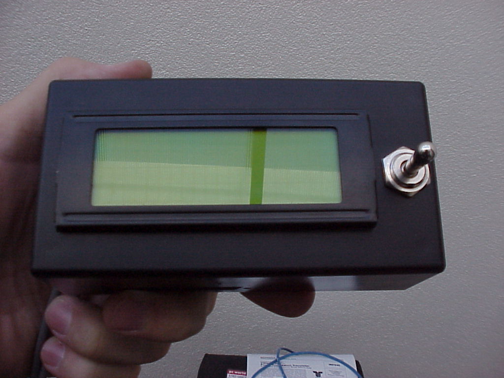
| Display and mode switch |
| Display and mode switch |
| "Backup" controller |
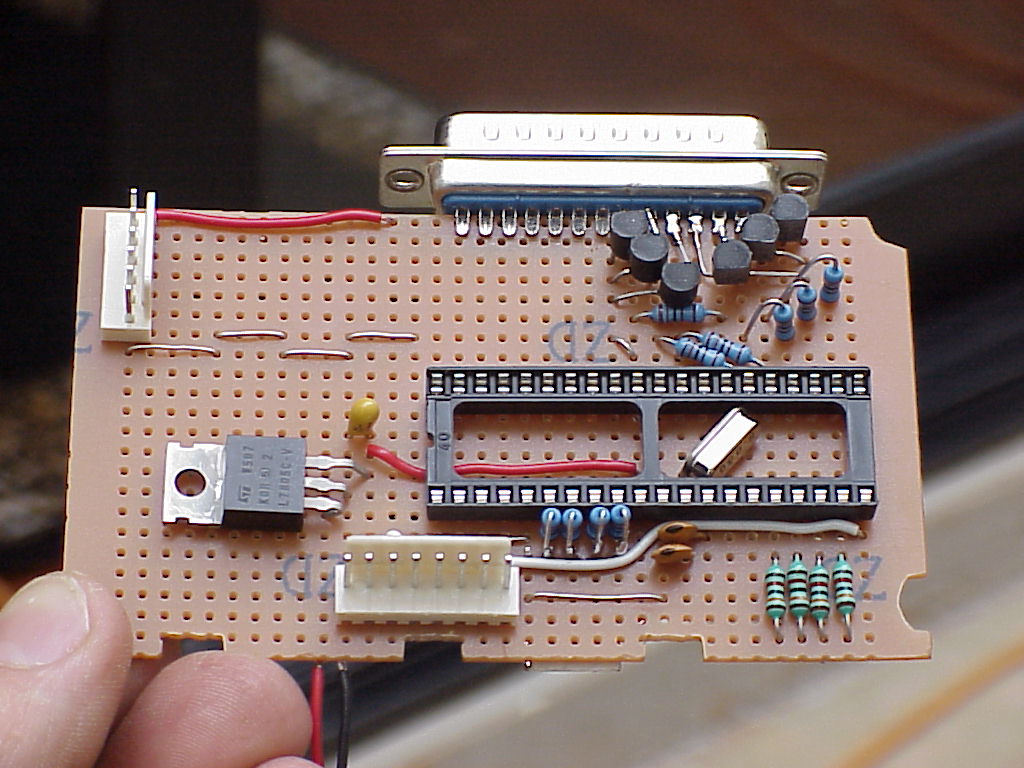
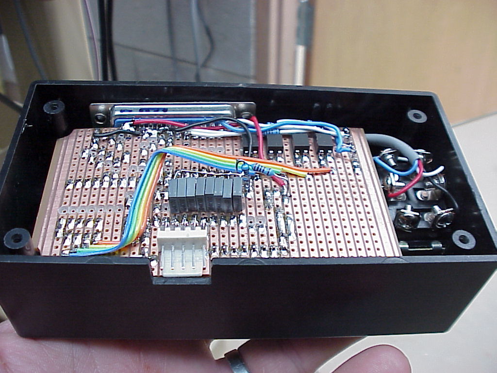
| Start of the veroboard prototype. All connections and power are through the D25 connector. The 6-pin conector top-left is for the mode switch, the 8-pin at bottom-centre is power and data to the LCD module. 8MHz crystal mounted under the IC socket out of the way. |
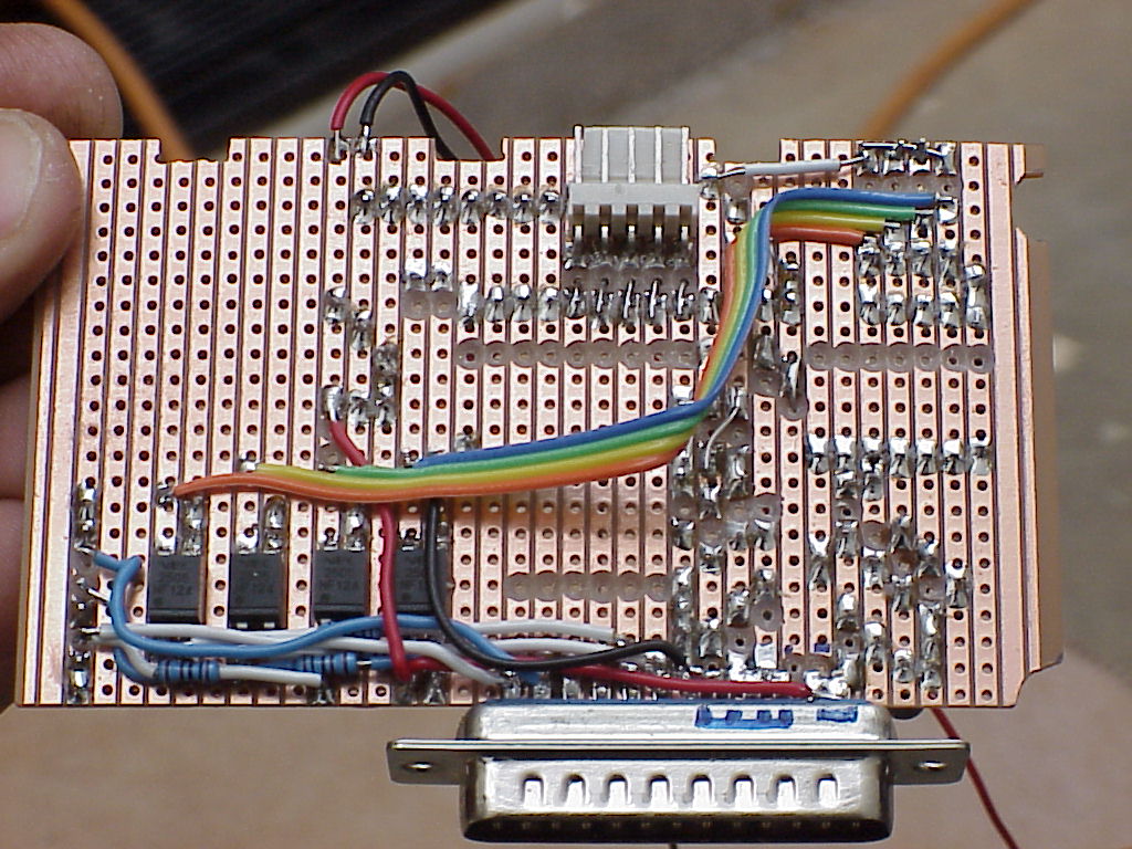
| The 5-pin connector (top-centre) is for the in-circuit programmer. Surface-mount opto-isolators mount conveniently on the copper side. Pretty rough construction, but it was meant to be a prototype... and I was making it up as I went (as usual) |
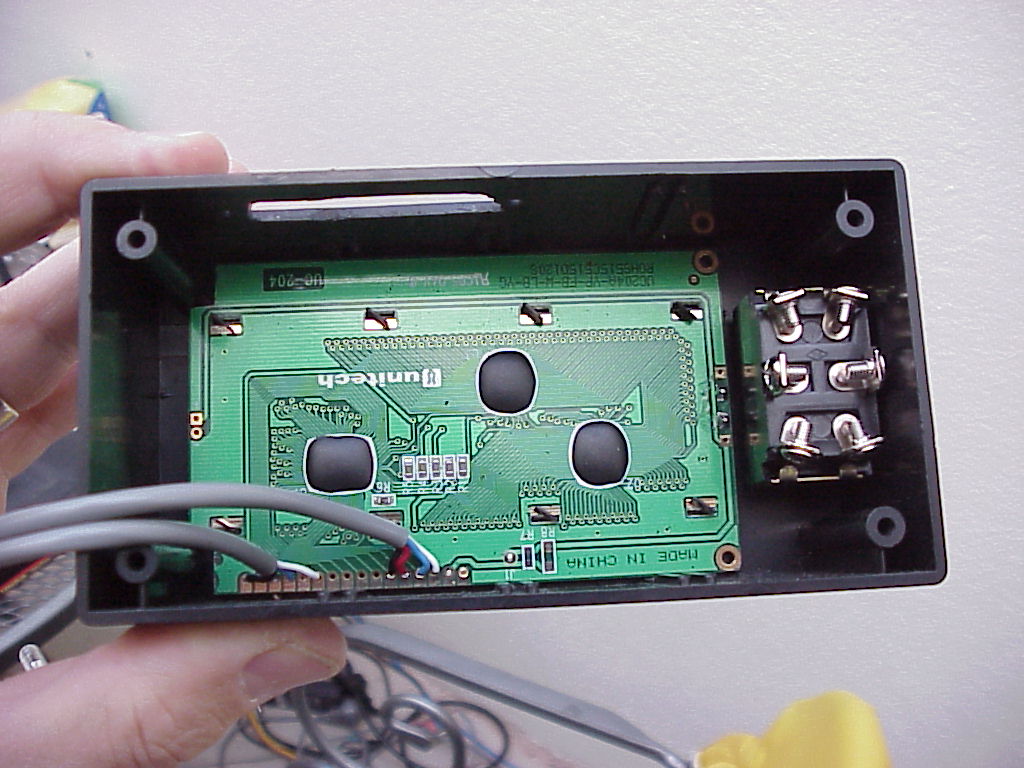
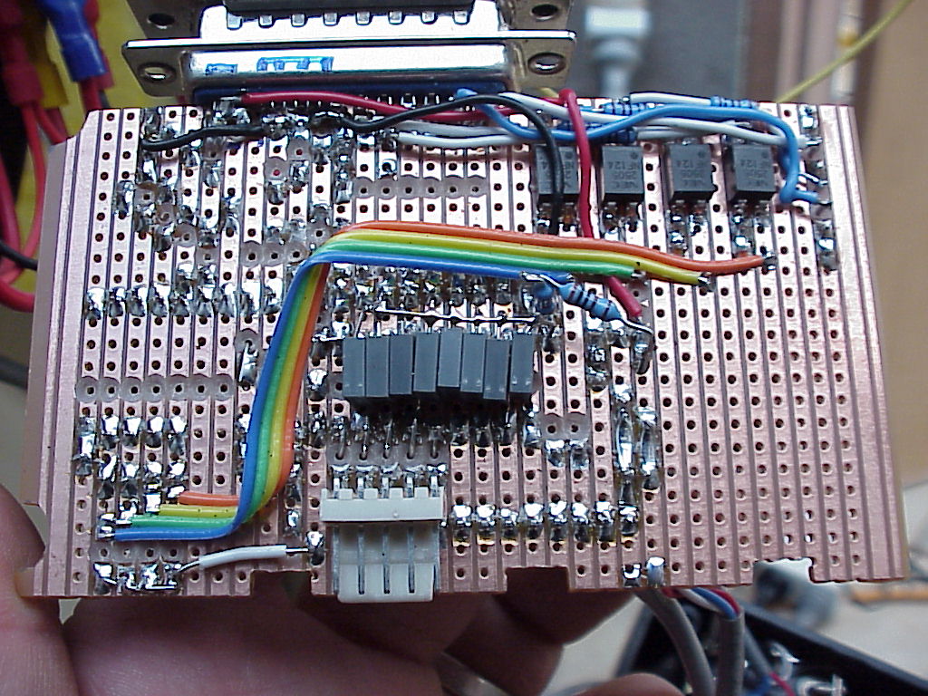
| Underside of complete board. A bit more mess, the most notable addition being all the small caps on the A-D inputs mounted under the board for convenience. |
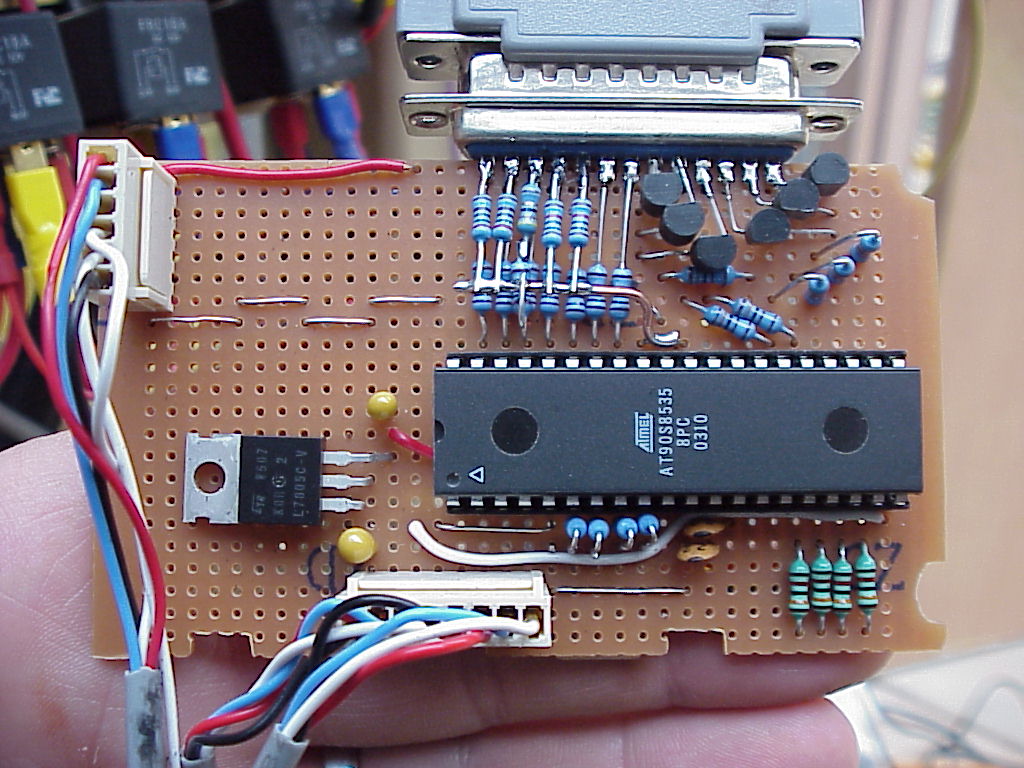
| Top of complete board. Note the resistors for A-D inputs. A series resistor and cap (underside) to A-D pin on chip, and the bias resistor for the thermisters themselves |
| Mounted in case. Note the cutout for the in-circuit programmer to update code without pulling it all apart. |
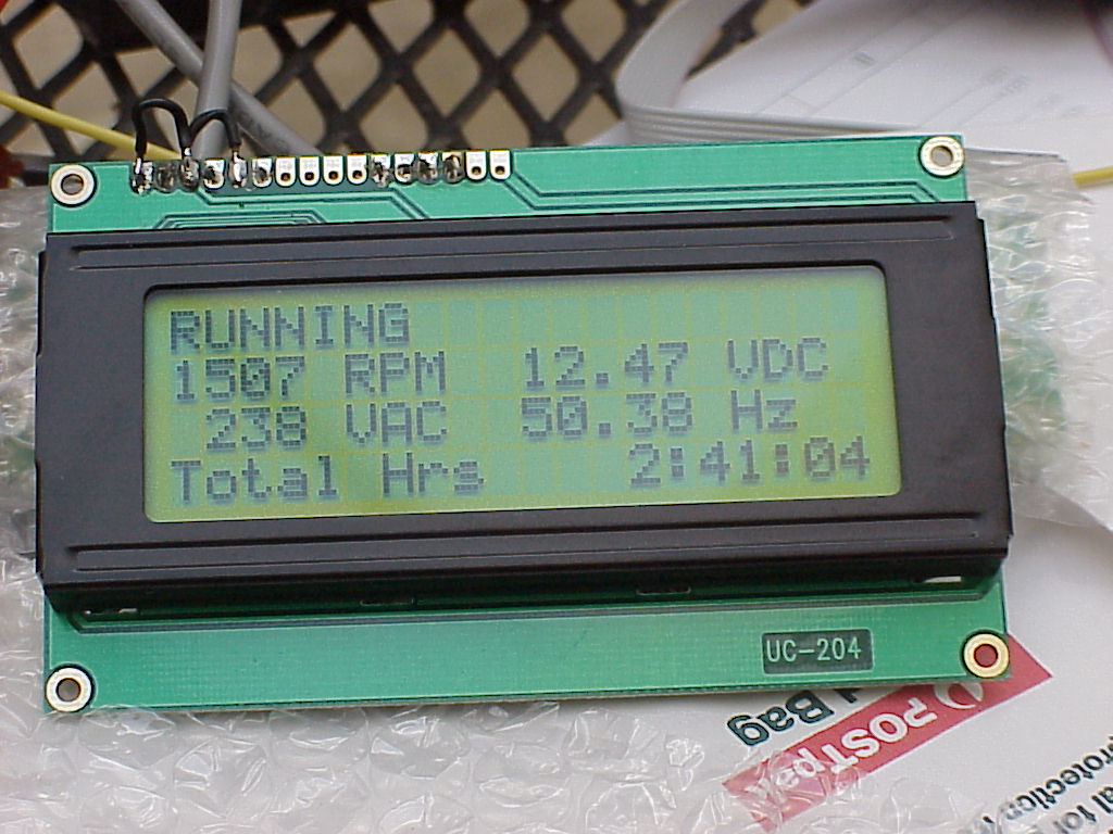
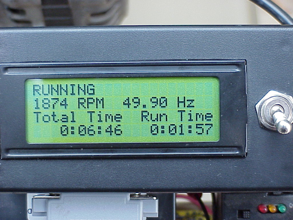
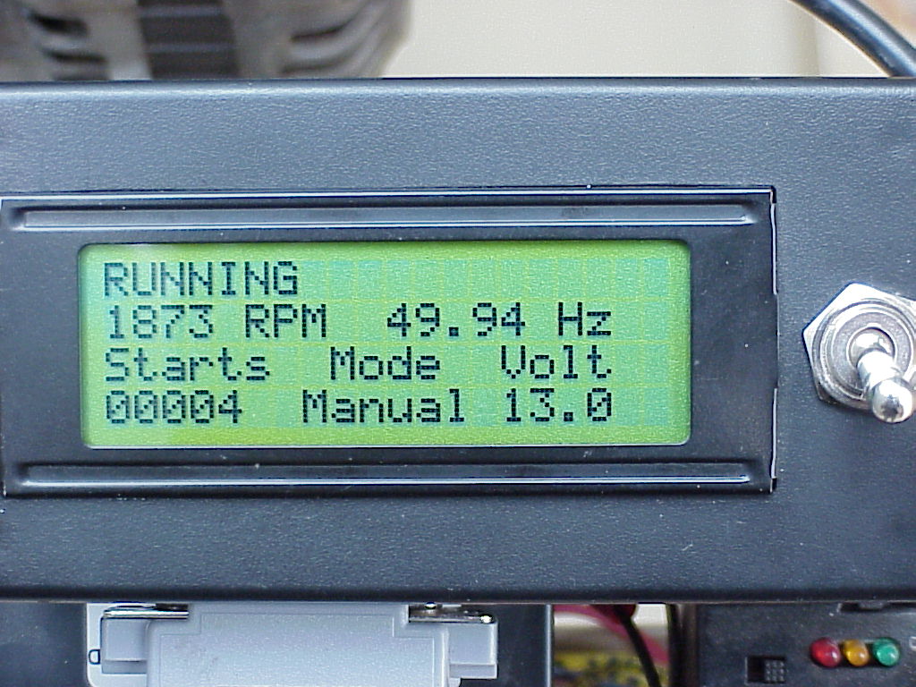
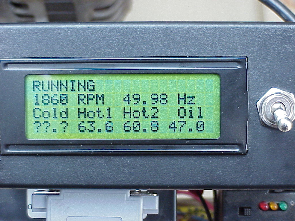
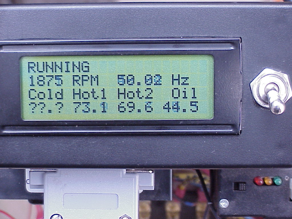
| Typical displays |
| Typical displays |
| Typical displays |
| Typical displays |
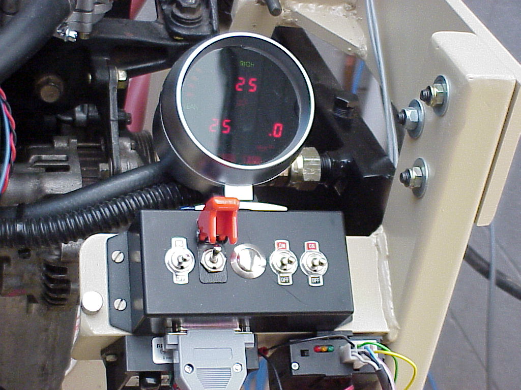
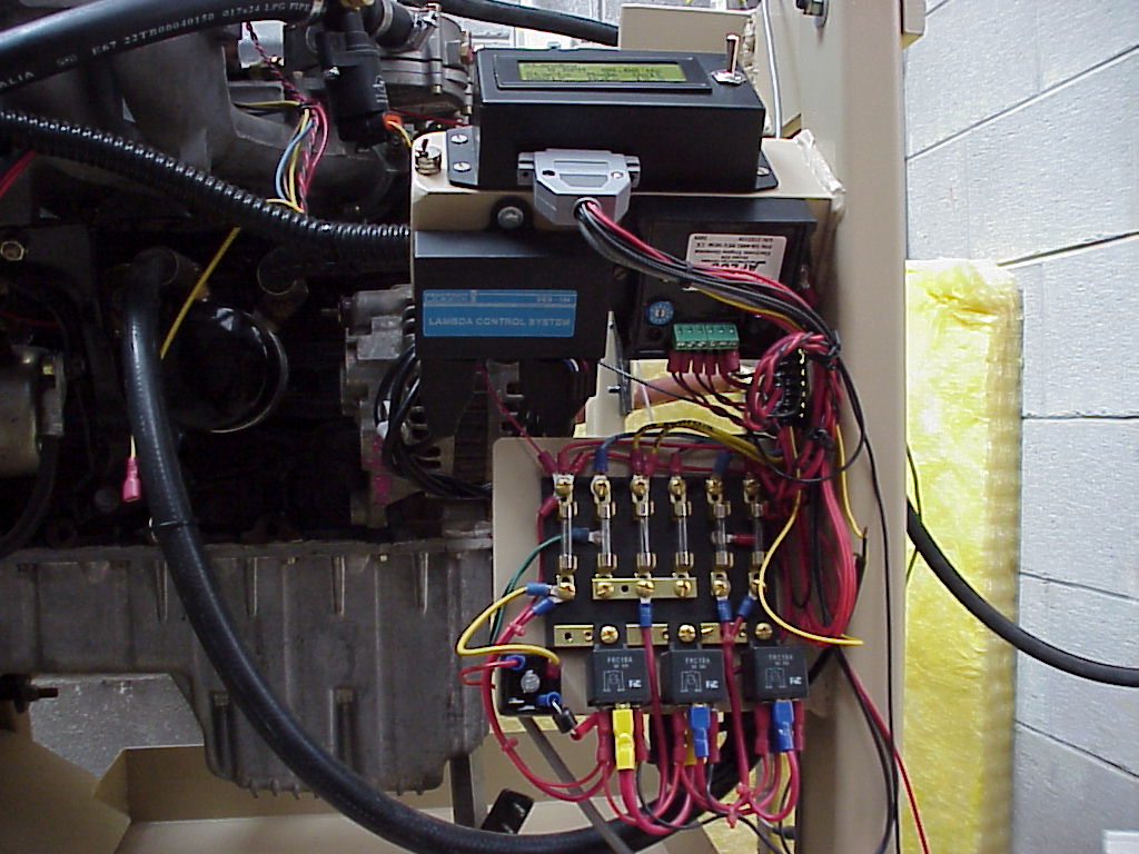
| Controller and fuse/relay panel, also visible the lambda (air-fuel controller) and electronic governor. |
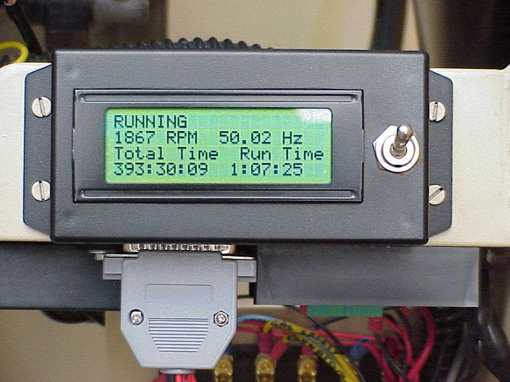
| Another shot of the controller while running |
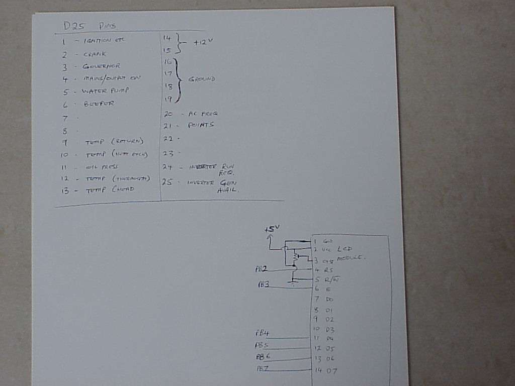
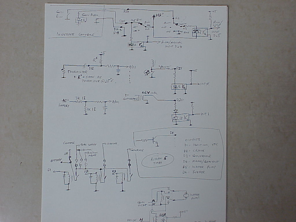
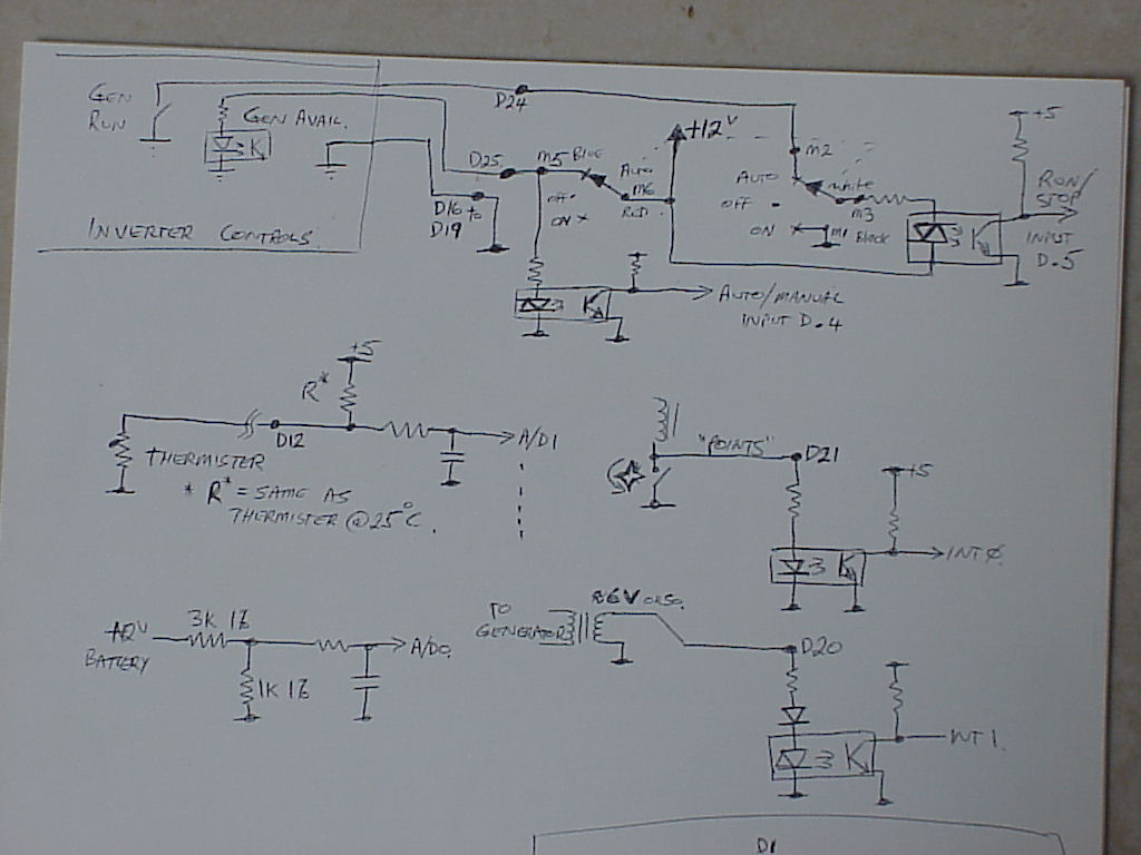
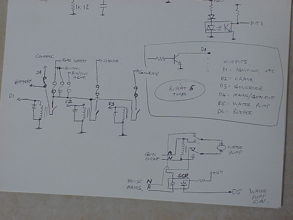
| Circuit diagrams part 1/4, 2/4, 3/4, 4/4 |