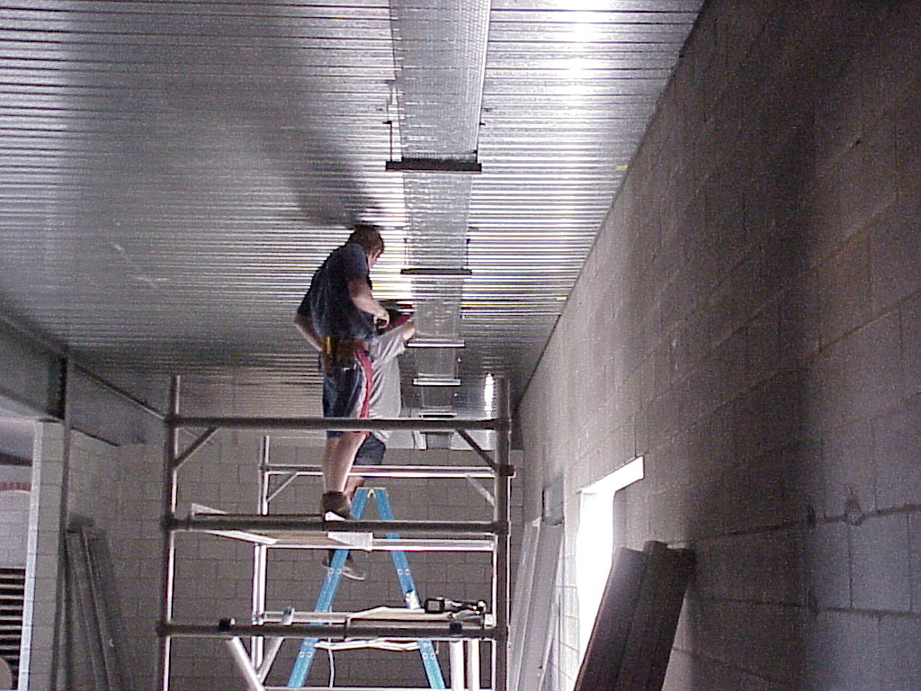
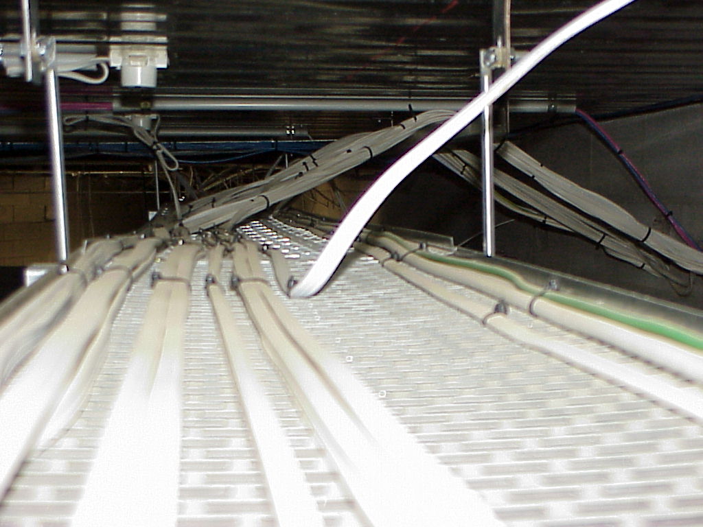
| Starting to put up the tray |
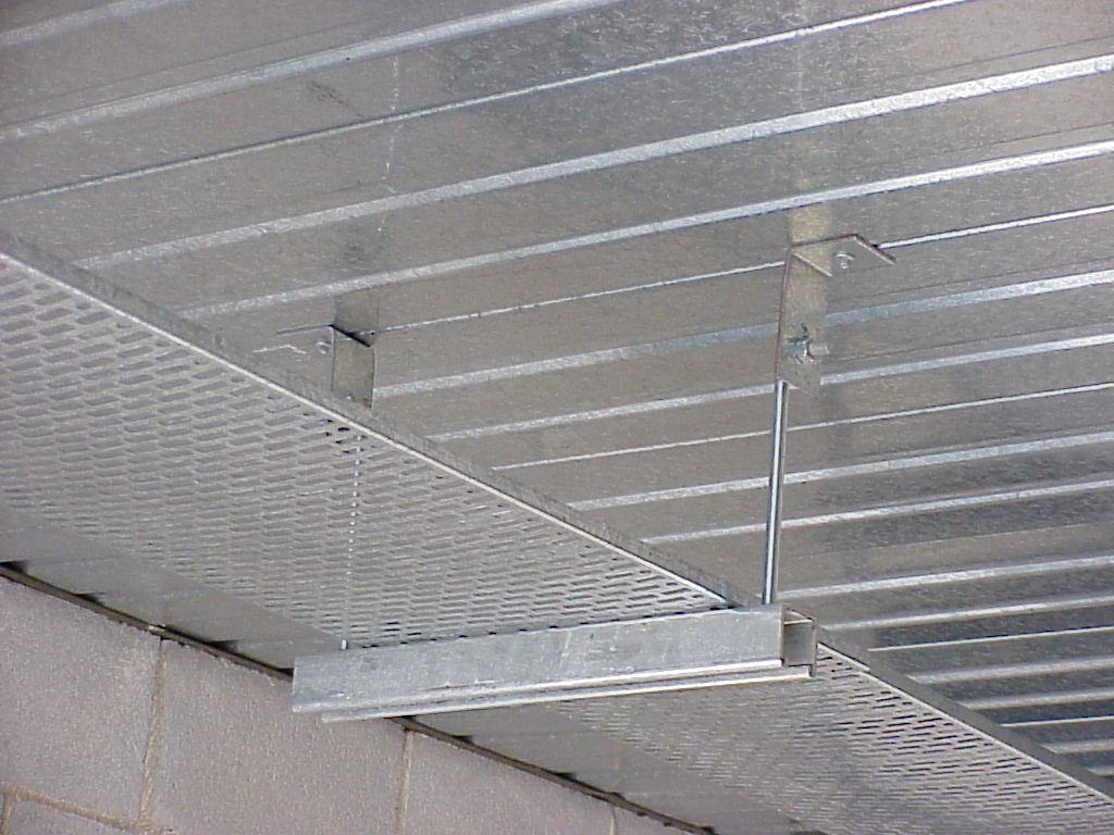
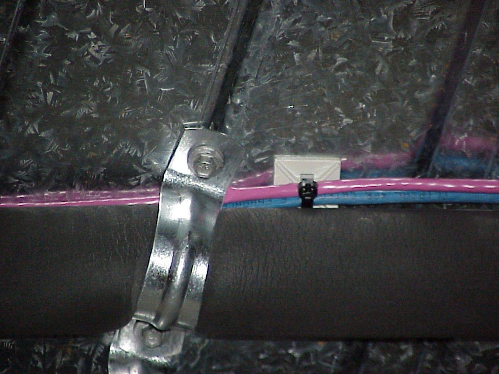
| Closeup, showing how the tray is held. Perlin brackets attach directly with tekscrews BETWEEN the condeck sheets, so there is no penetration (and thus no risk of water leaks), threaded rod welded to 10mm bolts holds lengths of unistrut. The tray is screwed at each support. |
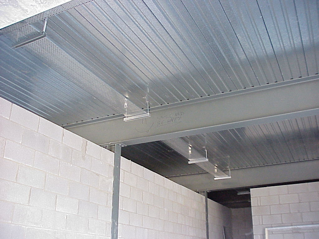
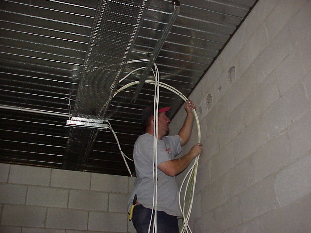
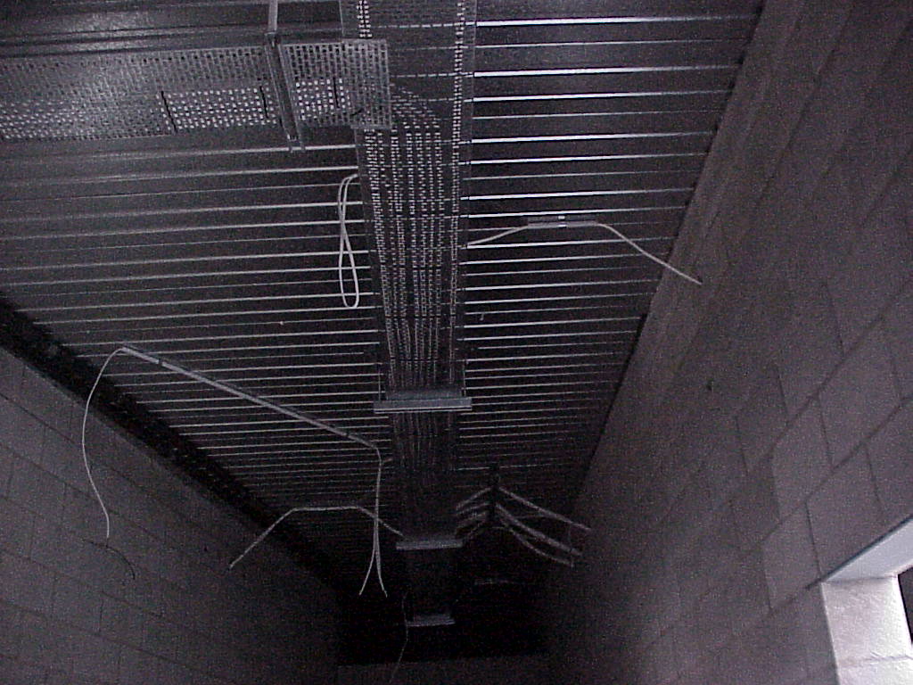
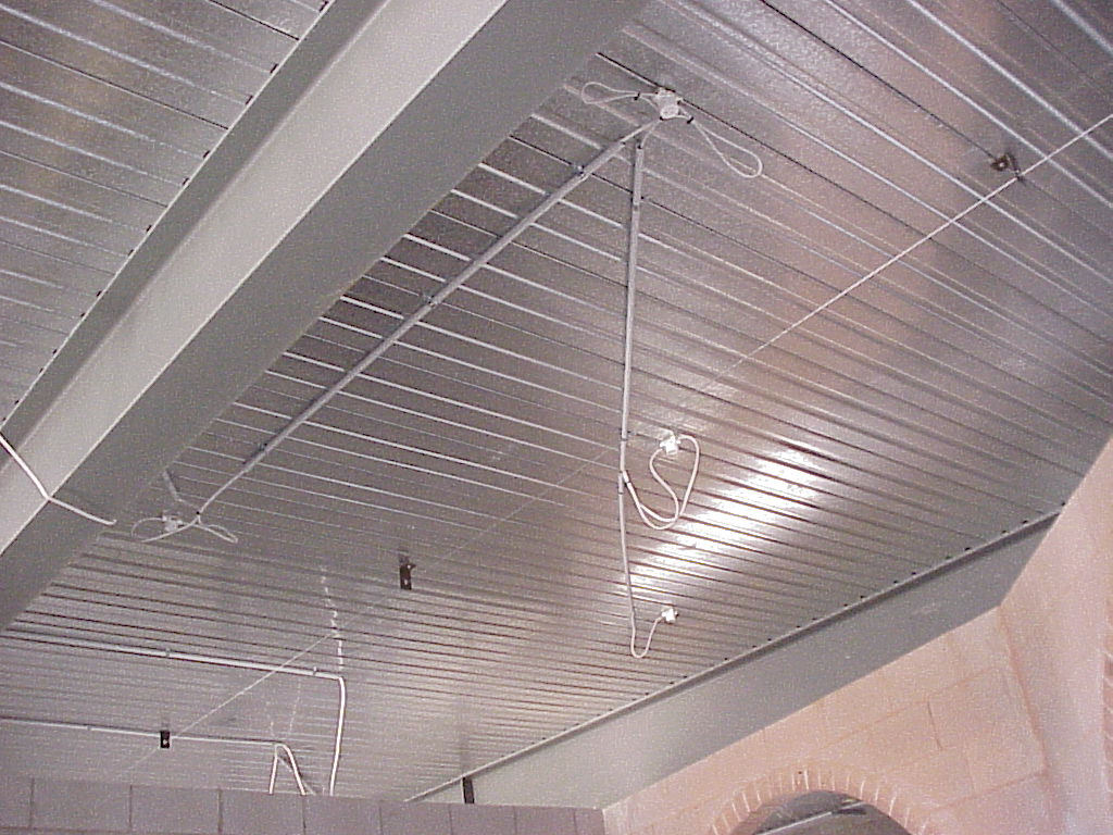
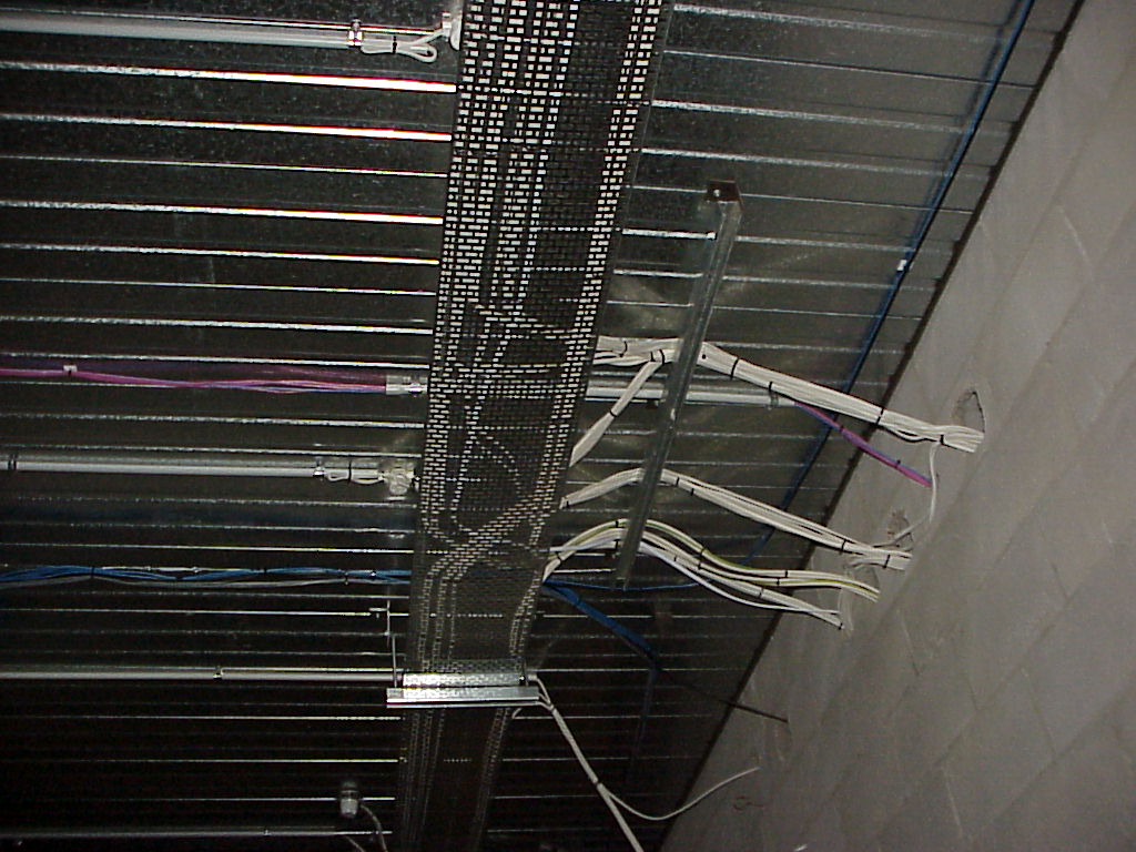
| Side runs of tray overlap, but stop where there are major structural beams. The cables will loop down under these beams, but hidden by the suspended ceiling which goes up later. |
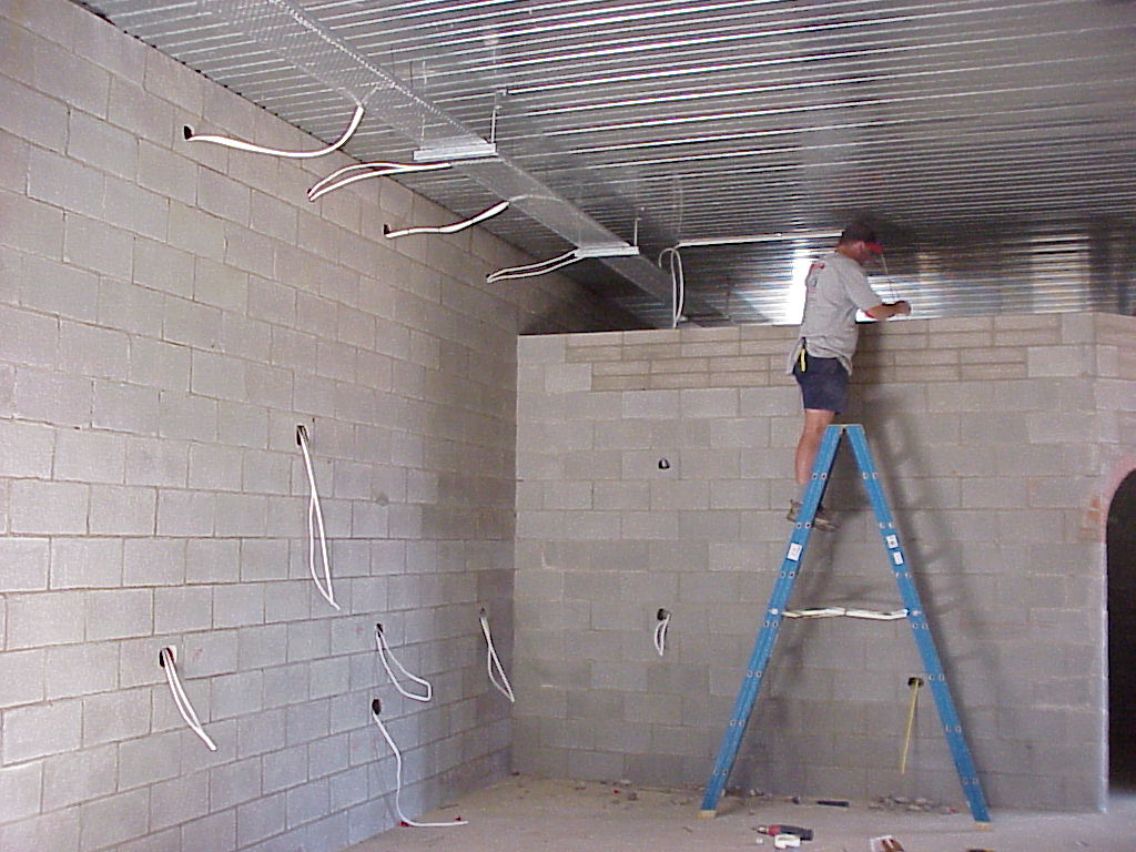
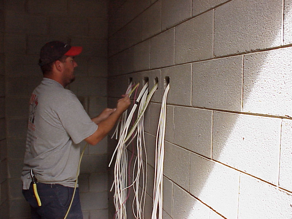
| Daniel runs a cable down an internal wall in the kitchen. All the cables run down wall in the concrete block cores |
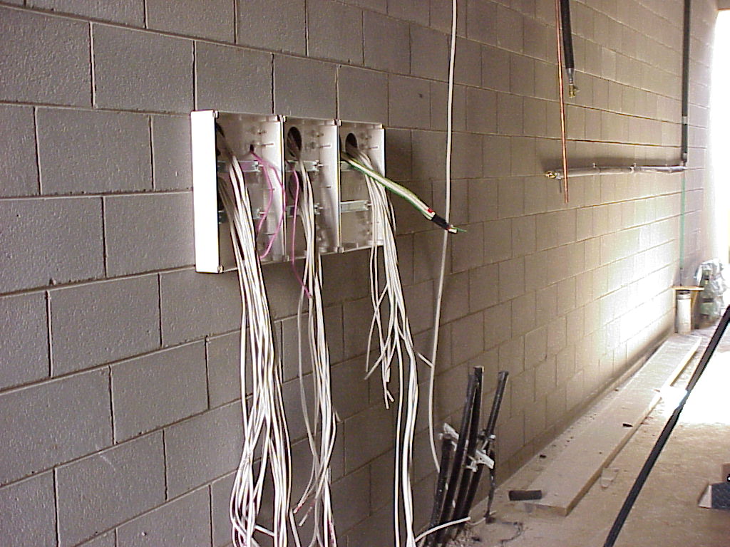
| Off the tray and over more unistrut as a support on the way to one of the sub-boards. 16mm cable between boards keeps voltage drop to a minimum. |
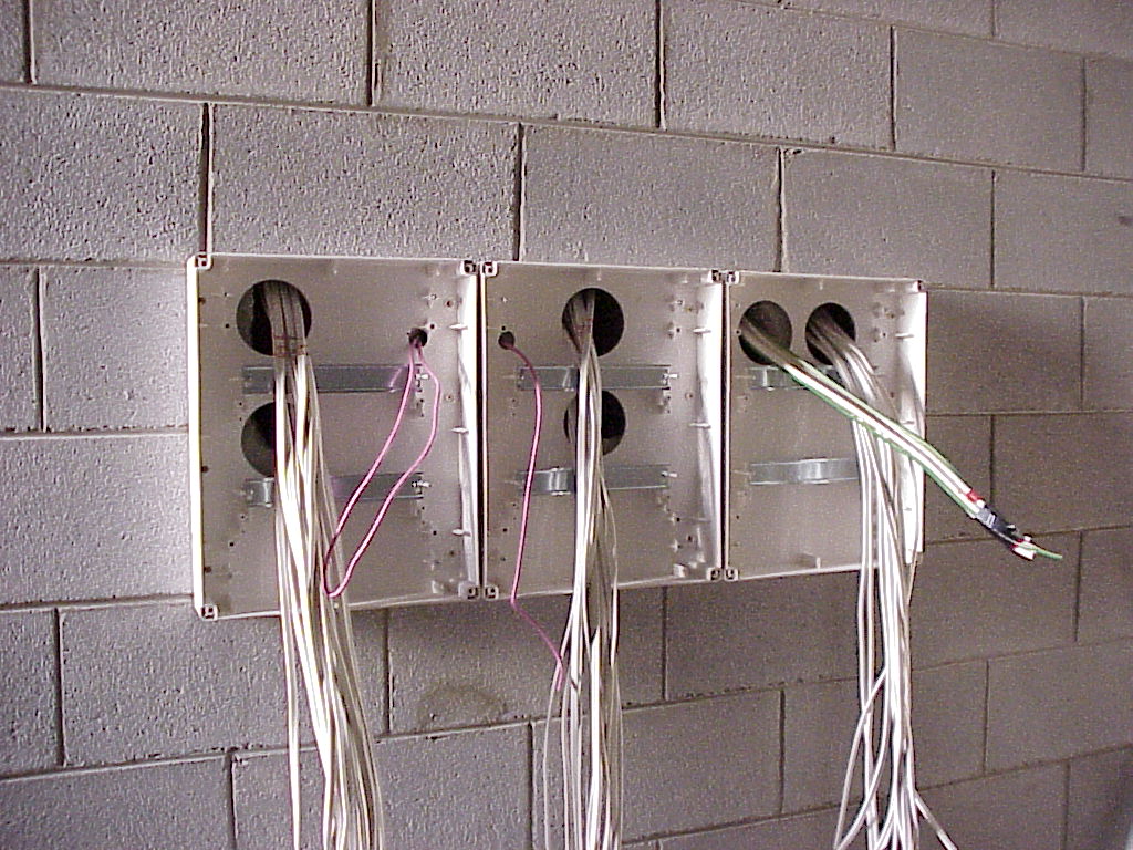
| Cables coming out the wall in the service way for sub-board 3. Notice the c-bus control cable is in its own "channel" keeping 200mm seperation from the other cables. |
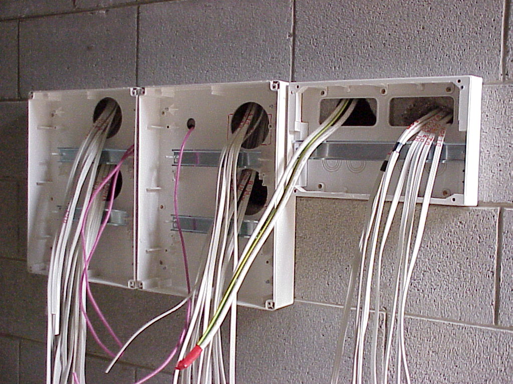
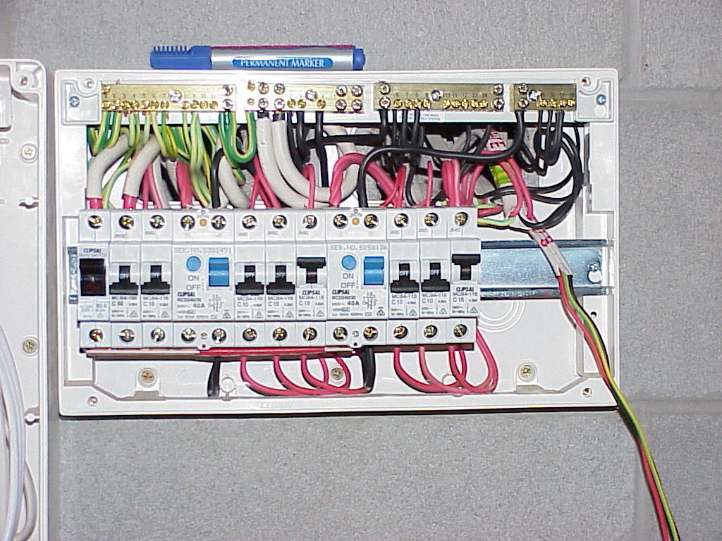
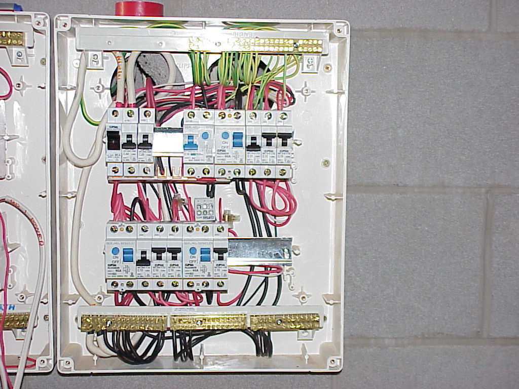
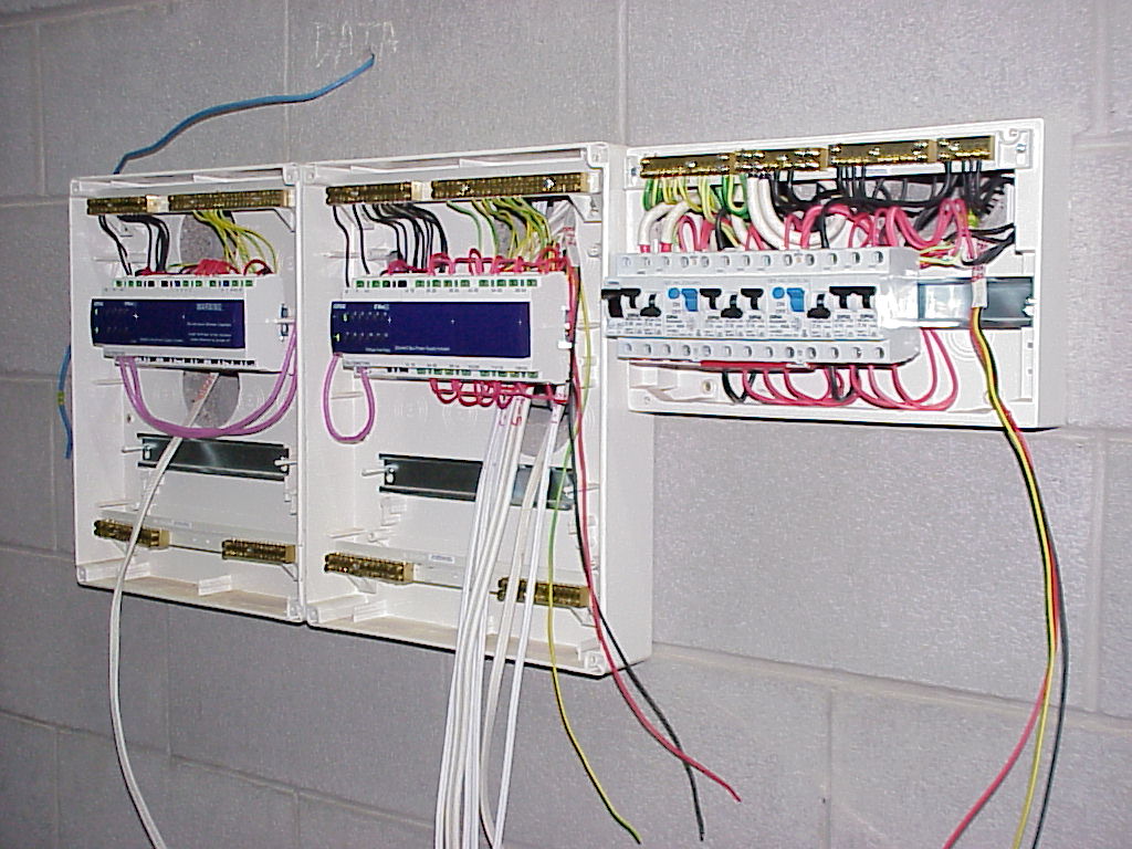
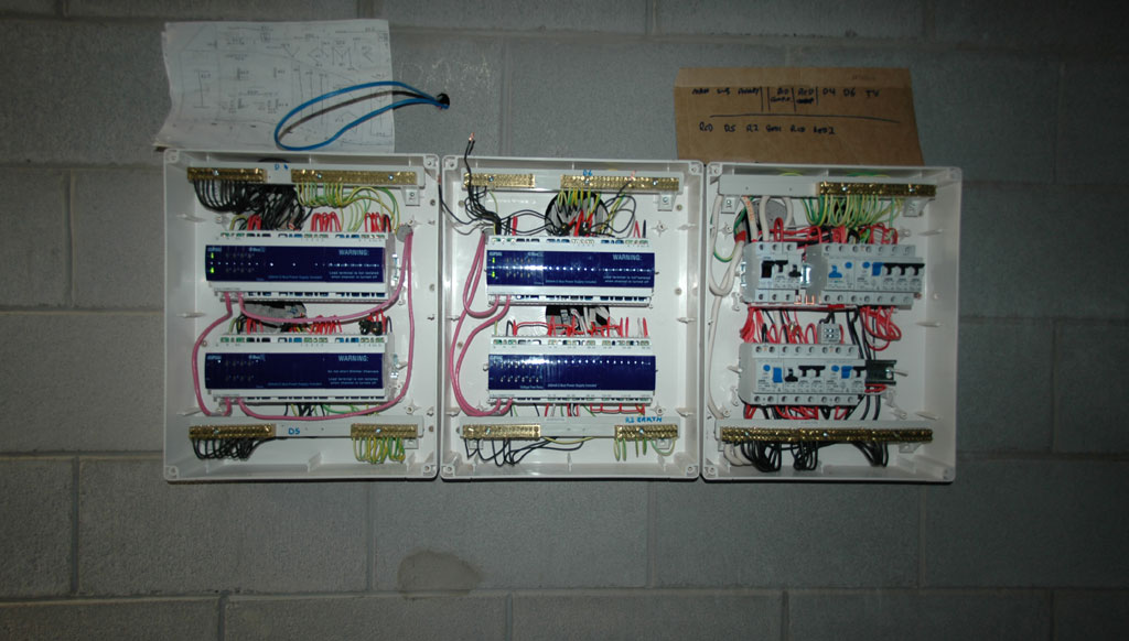
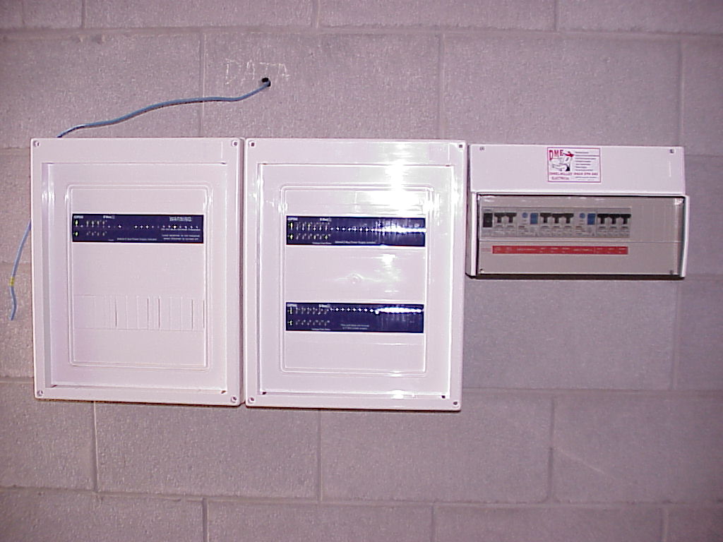
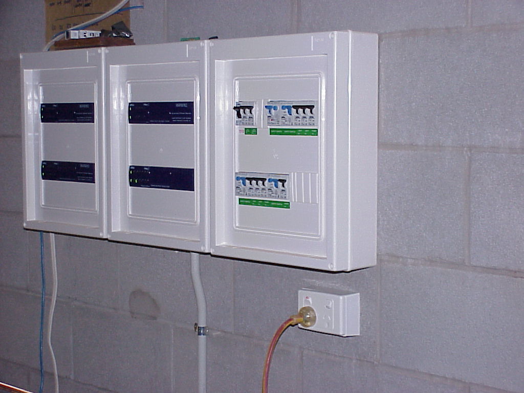
| Surface-mount 24M boards for the C-bus gear and a 12M for the MCBs, RCDs etc. Notice all the cables clearly marked! |
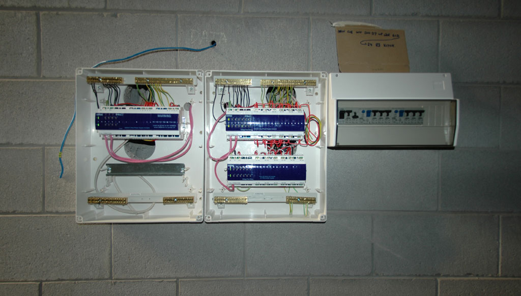
| Another sub-board. More breakers required here, so 3 24M boards were used. |
| |
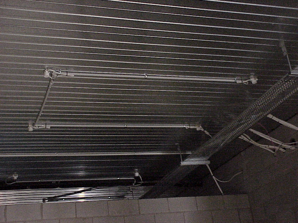
| Some of the cables on the tray, all clipped. |
| |
| All the downlights have been fitted off with fan bases. They're quick to fit off (expecially the insulation-displacement (crimp-on) ones!), which gives us maximum flexibility later, and means few wires dangling in the way of the next lot of trades through. (Where pendant fittings were going, we left the cables long) |
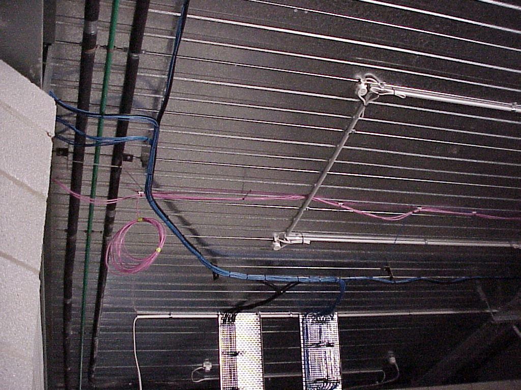
| Extra length was left at each fan base incase we ever needed it, but it was tied up with cableties. The catenary wire will support the CAT5, security and c-bus control wire |
| |
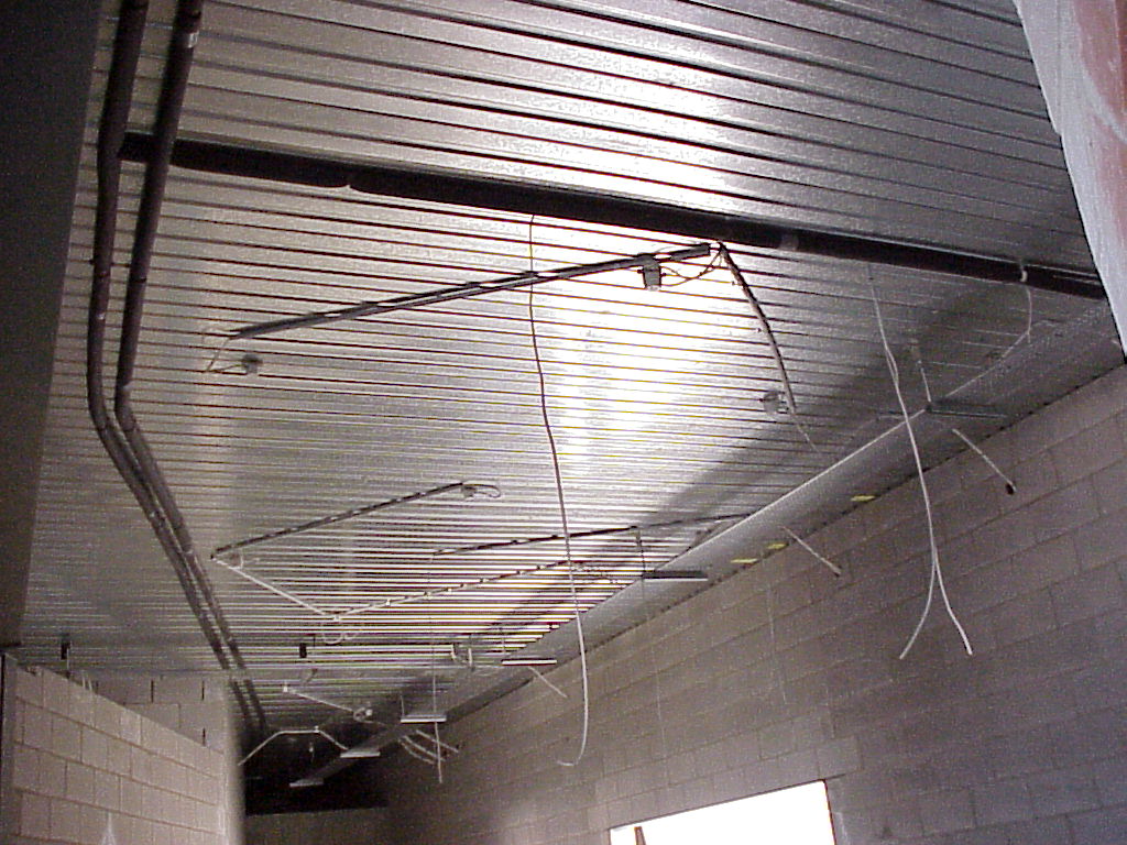
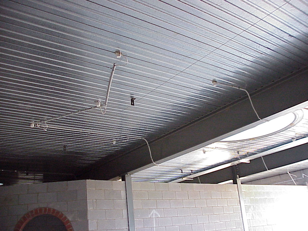
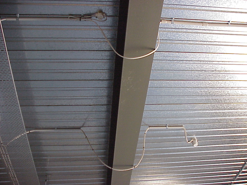
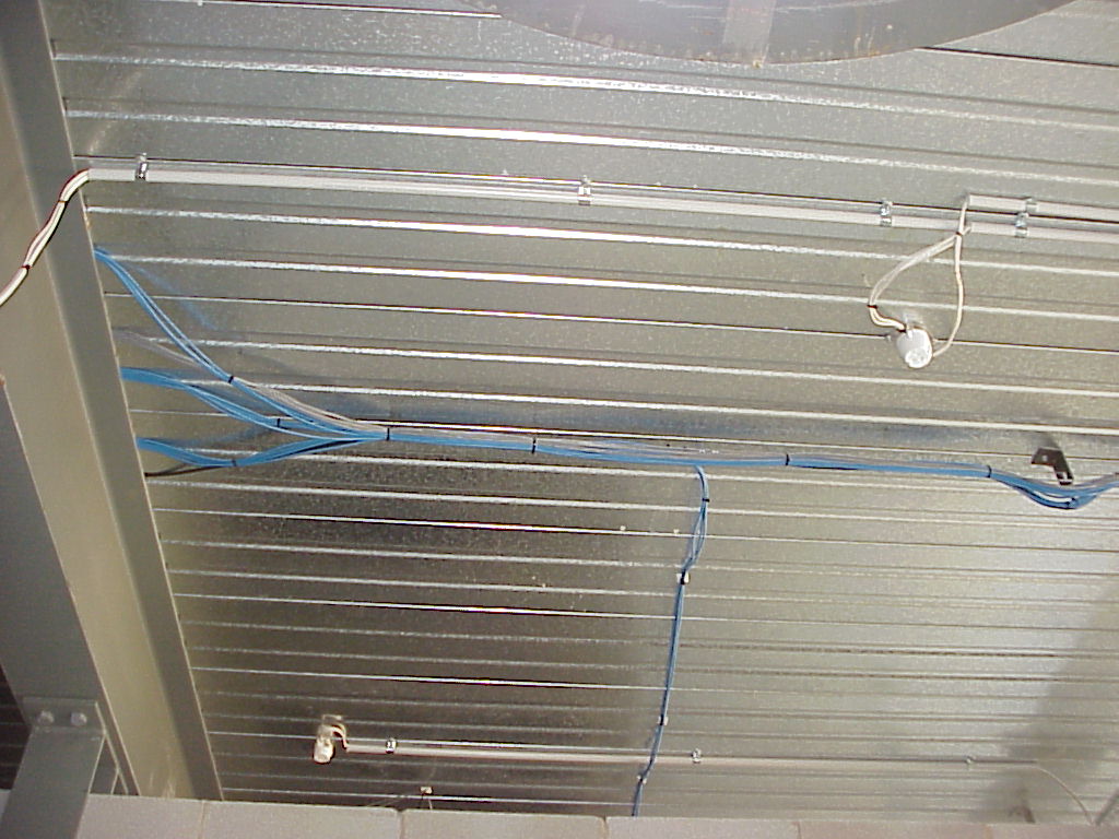
| It's a little inelegant, but safe and convenient to pass under the beams, rather than trying to squeeze between the condeck and the beam. |
| |
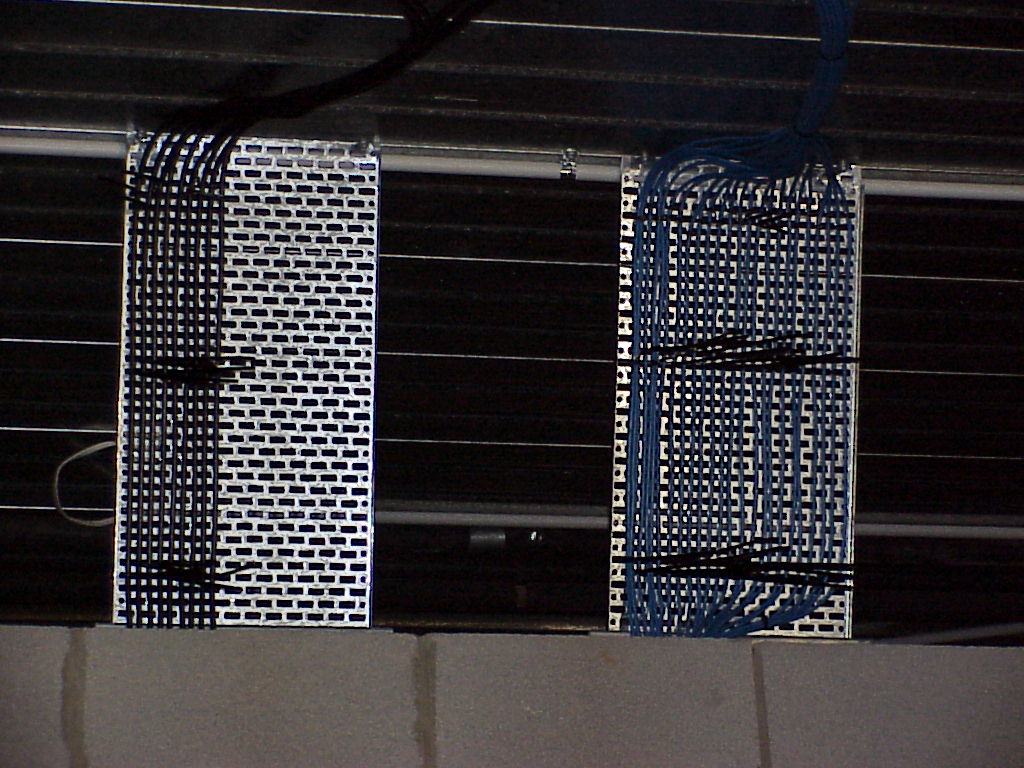
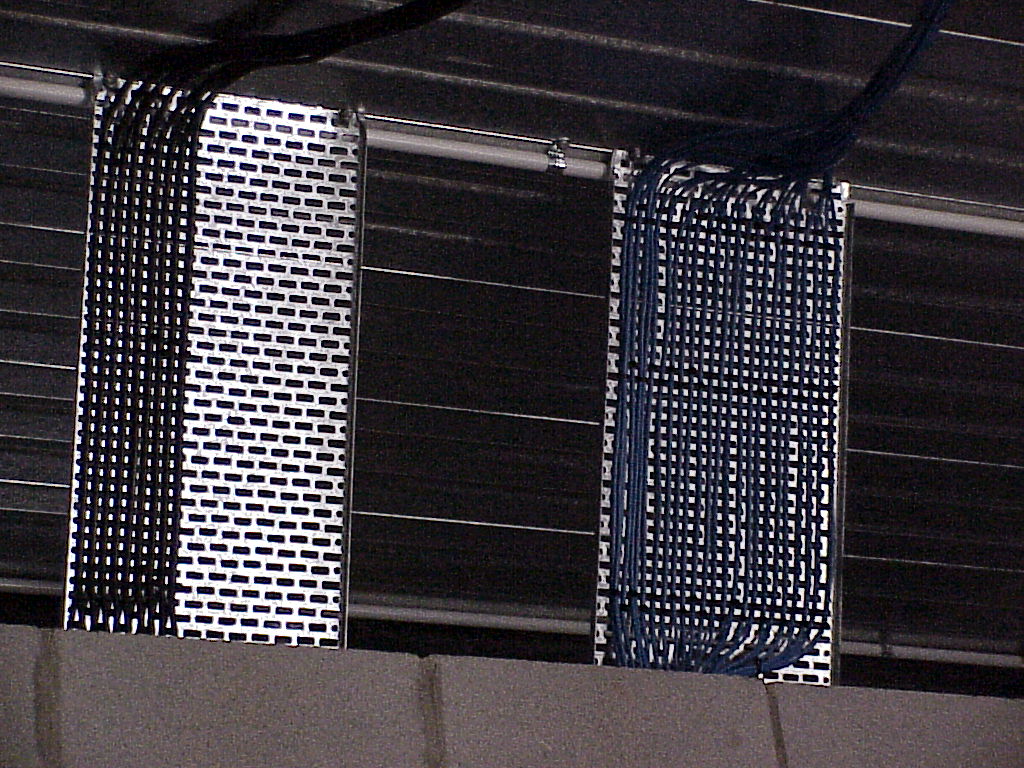
| Keeping the security, network and MATV coax tidy was a snap, with some offcuts of tray. Cableties not yet clipped, but still running cables! |
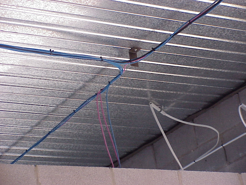
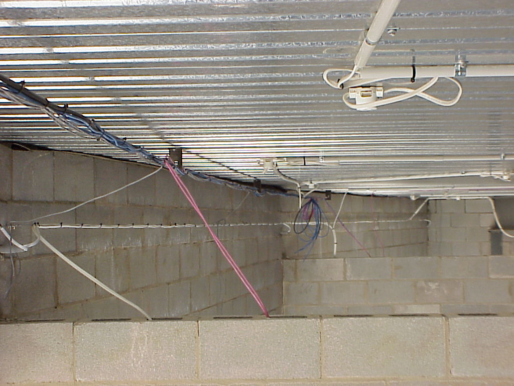
| Lots of seperation between mains and everything else. Where cables needed to cross (like the c-bus getting to this sub-board), its crossed at right-angles, and with conduit. Also clear is how the network and MATV are hung off the catenary. |
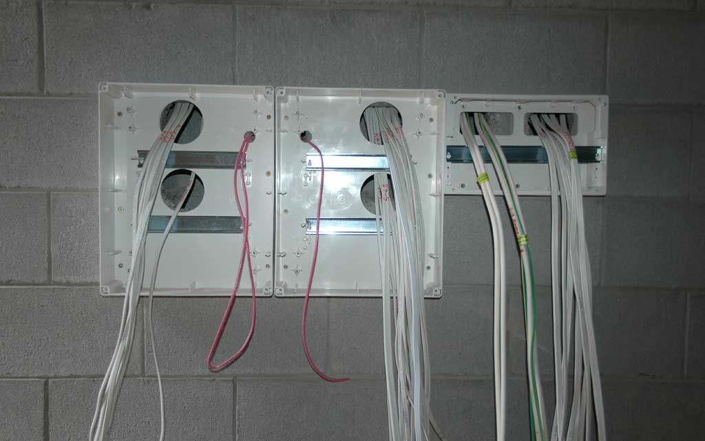
| Cbus cable was run to places where we MIGHT want a switch later, even if there is no plan for it in the forseeable future. Minimum seperation is still maintained down the wall by using seperate channels down the blockwork. |
| Cableties clipped, although security cables not yet run |
| Who says plumbers have brains? Our cabes were there first, but the plumbers just stuck their hot water (up to 100 deg C) over, through and around the cabling and stuck saddles wherever tey felt like - without bothering to move the cables! This sort of stupidity took a day to fix. ARGHH! |
| Cables disappearing into the wall for one of the sub-boards. |
| Some of the security cabling visible, using the same catenary wires as the data cabling. |
| All nice and neat (although some of the sensor wires (grey) seem very close to the mains cables, its only to keep the loose ends out of the way until the sensors are installed) |
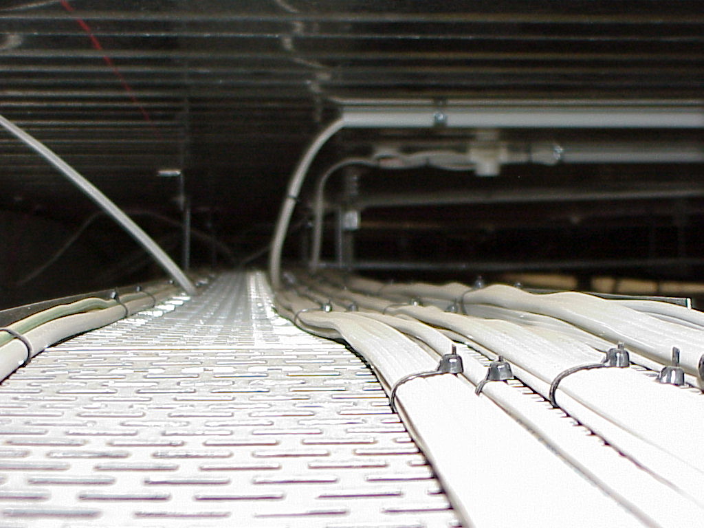
| Photo looking down along the tray |
| And back the other way |
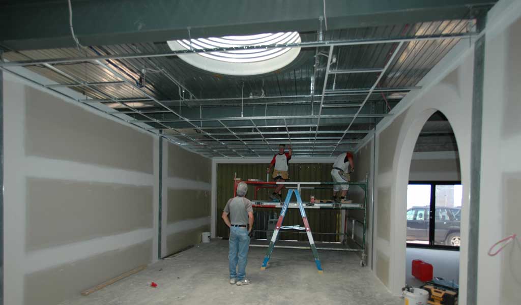
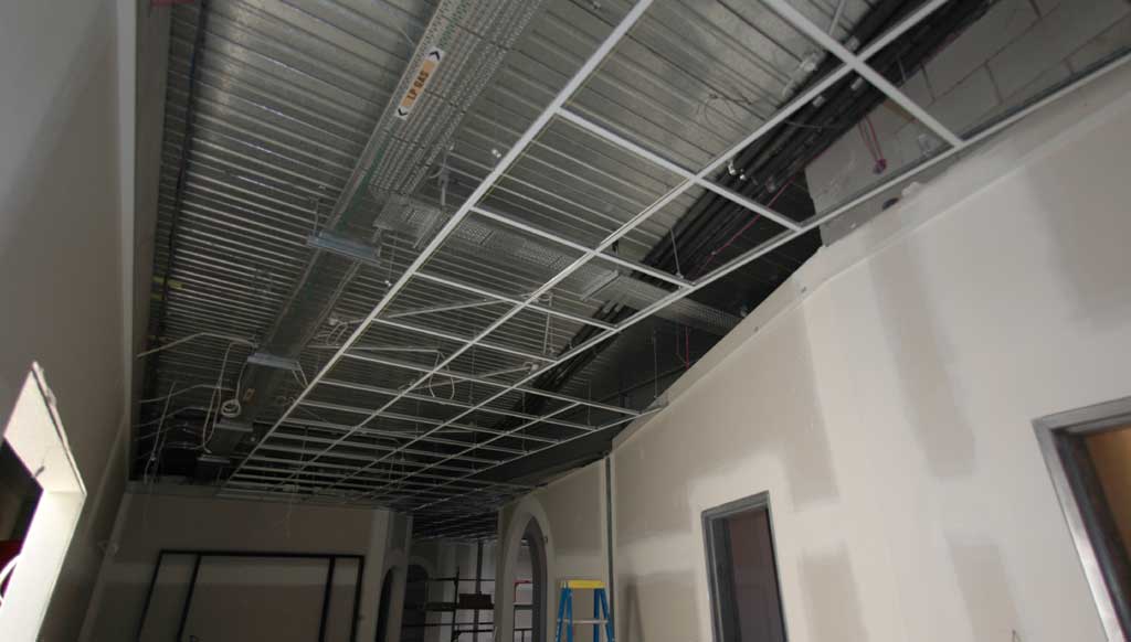
| The suspended ceiling grid starts to go up |
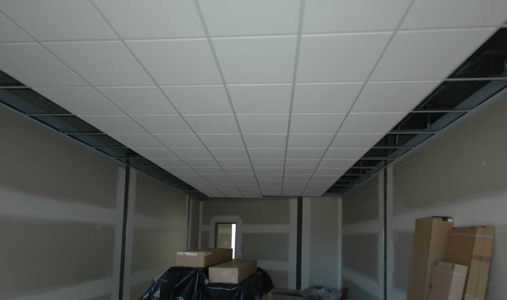
| And when the acoustic tiles go up, all the cable work dissappears! |
| |
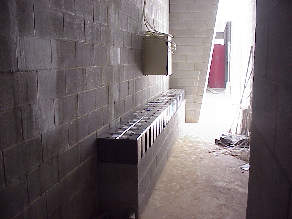
| The main "power" room. 48 cells, each 2V, 300AH as two 48V banks supply the 5KVA (10KVA peak) pure-sinewave generator-interactive inverter (on the wall, left) |
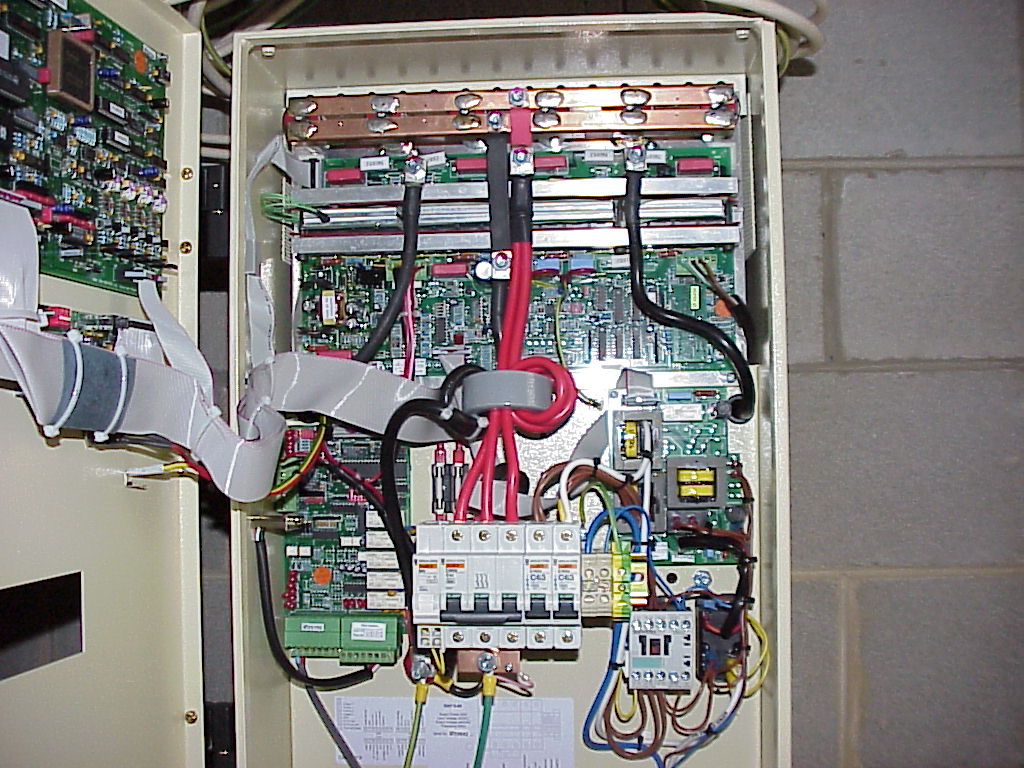
| Inside the inverter |
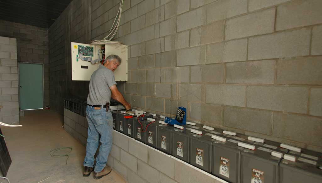
| Starting to wire up the inverter |
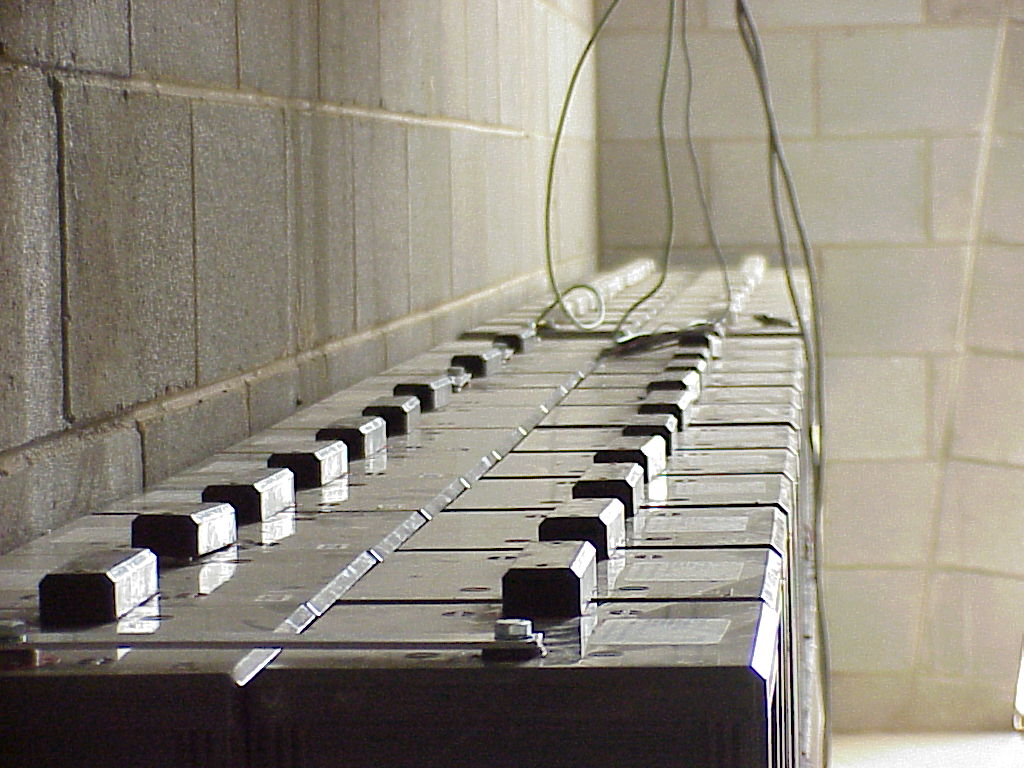
| Batteries with interconnect jumpers in place |
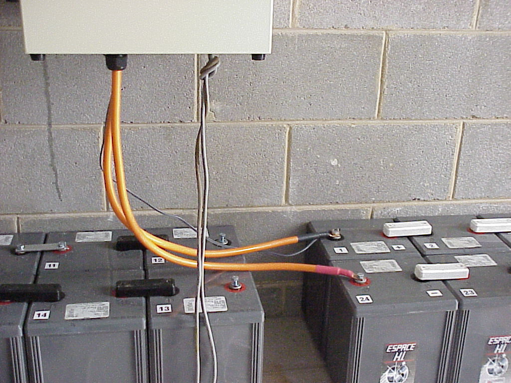
| First battery bank connected |
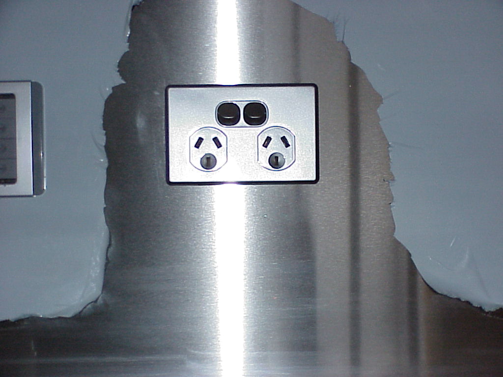
| Starting to fit-off. The "Satin-Chrome" wall plates go nicely with the brushed stainless splash-backs in the kitchen |
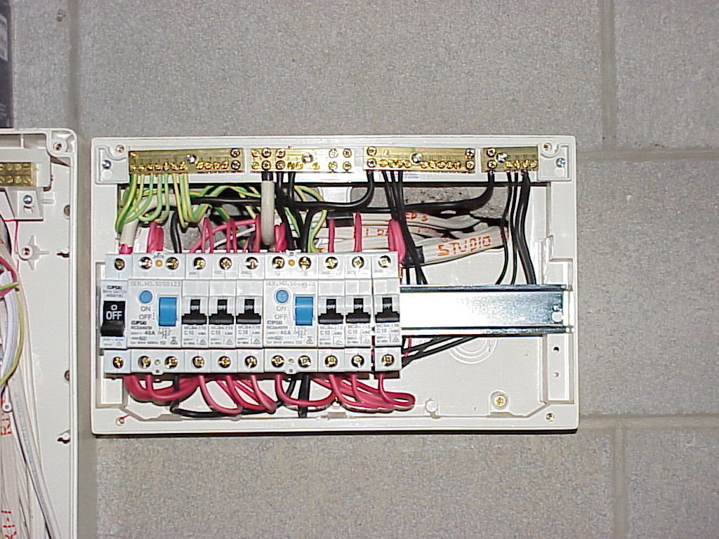
| Fitting-off of the sub-boards |
| And again. |
| And again. Have to finish all the mains stuff before we even consider starting on the c-bus stuff! |
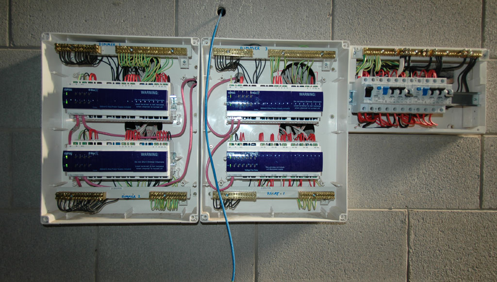
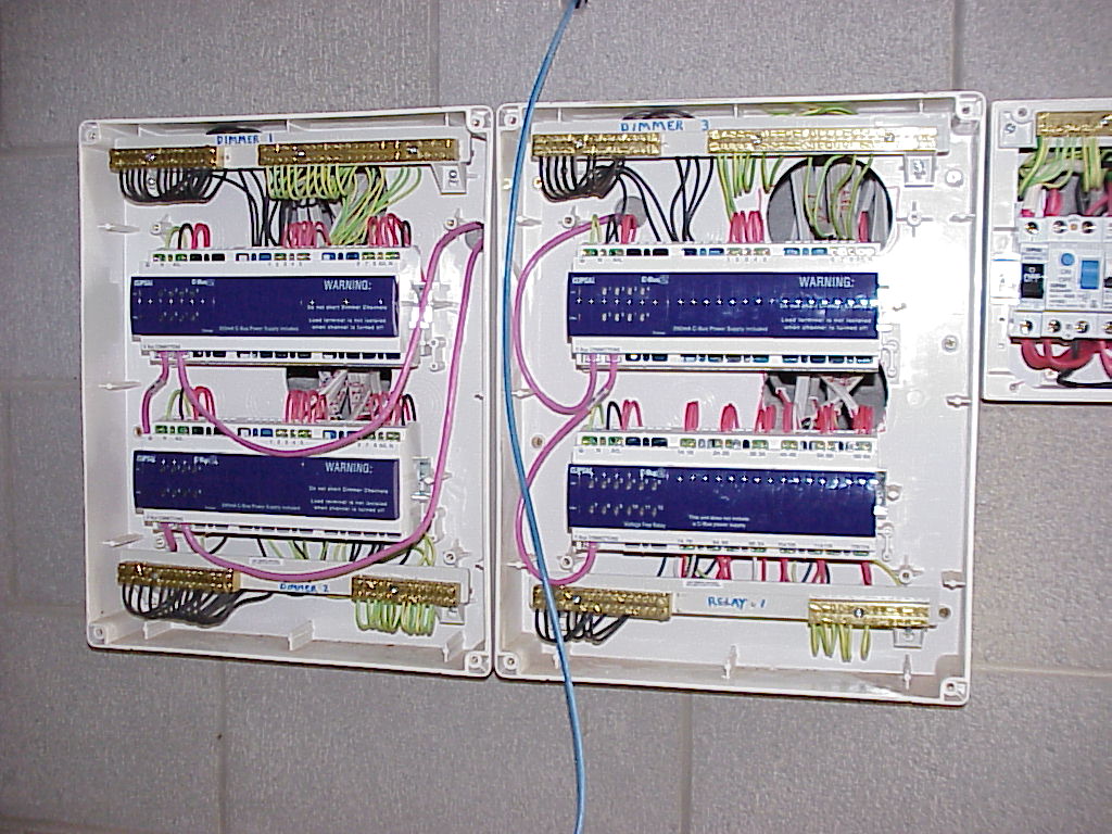
| NOW we can start the c-bus. |
| |
| |
| |
| Nearly finished, and doesn't it look neat! (No, that network cable doesn't belong there, it gets fitted off soon, above the sub-board) |
| |
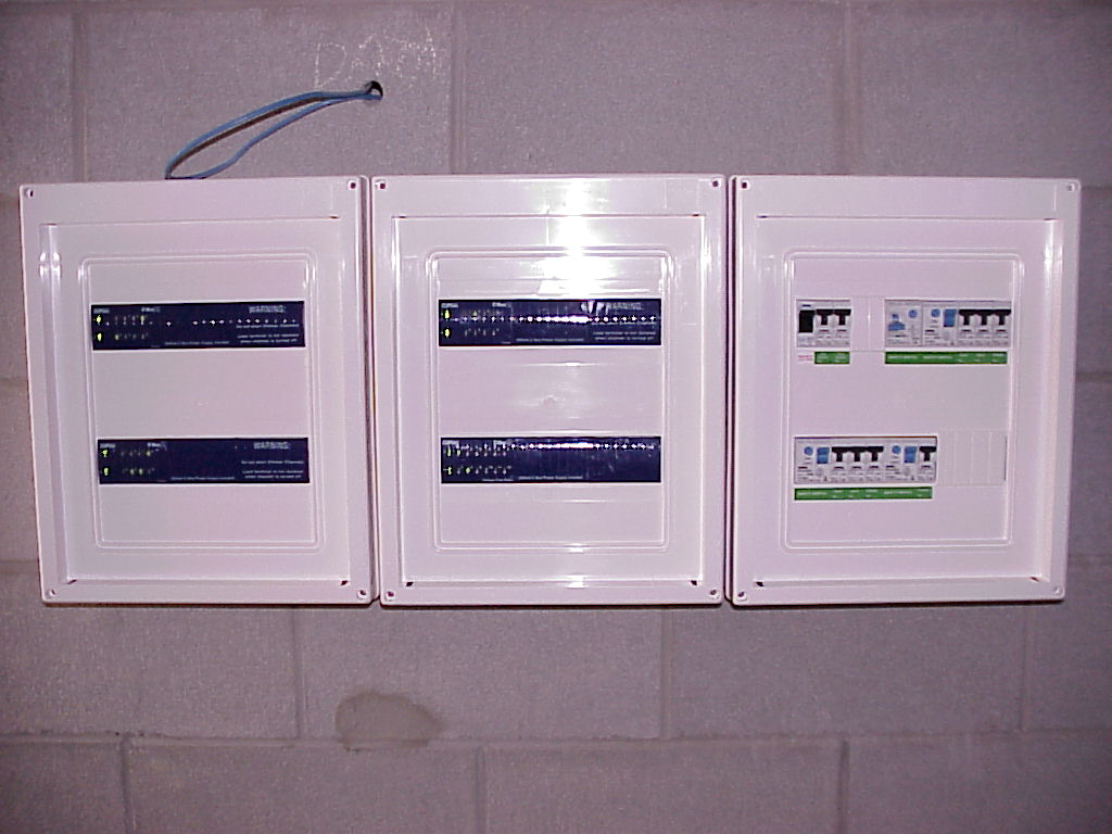
| Switchboard covers on. Do I put the doors on, or not?! We decided "or not" and it hasn't been a problem to date |
| |
| |
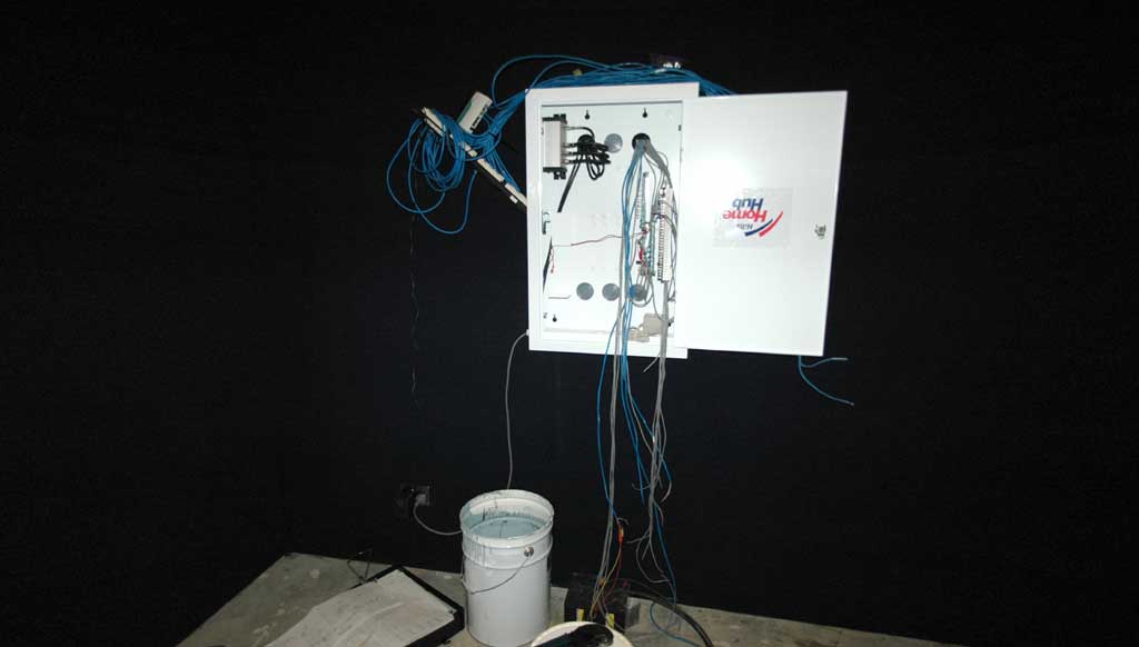
| Starting to work on the MATV and security next |
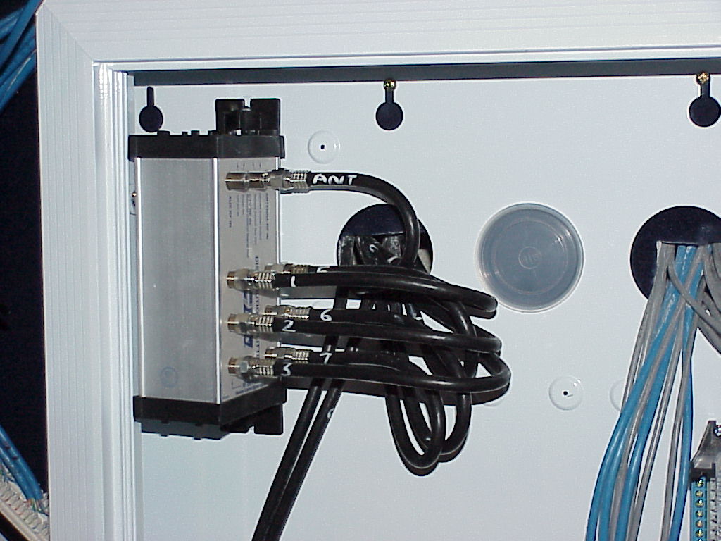
| The Hills system worked out much more conveniently and about half the price (sorry clipsal!). The coax is right on the minimum bend radius, I tidied this up a bit after I took the photo |
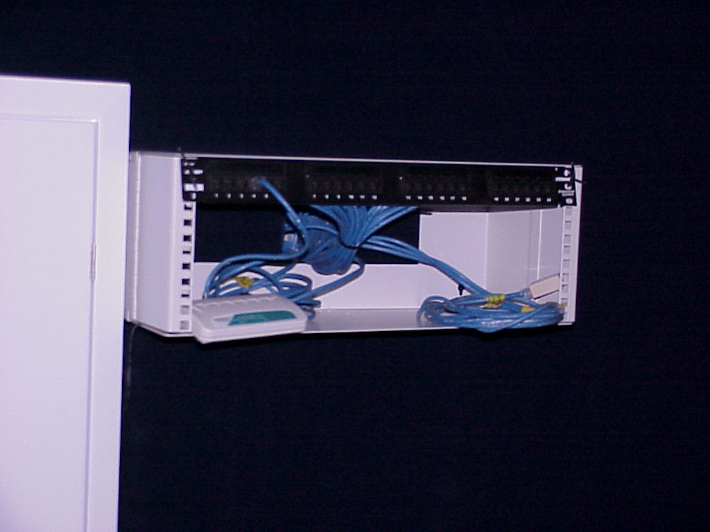
| The first 24-way patch panel in a mini frame, and a small switch just to get me on the air while I work. Another patch panel went in shortly after, and the 24 port 1RU switch, the terminal server and two VoIP units. The Phone system is mounted below. |
| The floor finally sanded and sealed, just hardening off. Kitchen electricals finished except for the stove and range-hood |
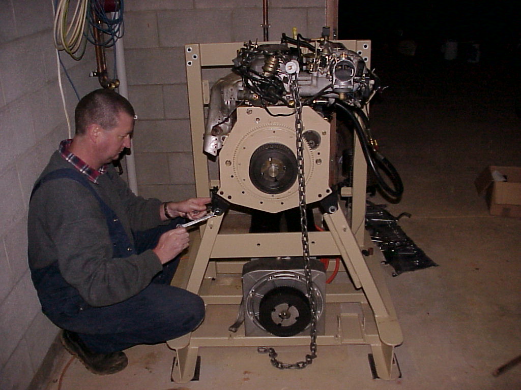
| My mate Mark helps position and do up the engine-mounts for the generator set that powers the place when the batteries get low. |
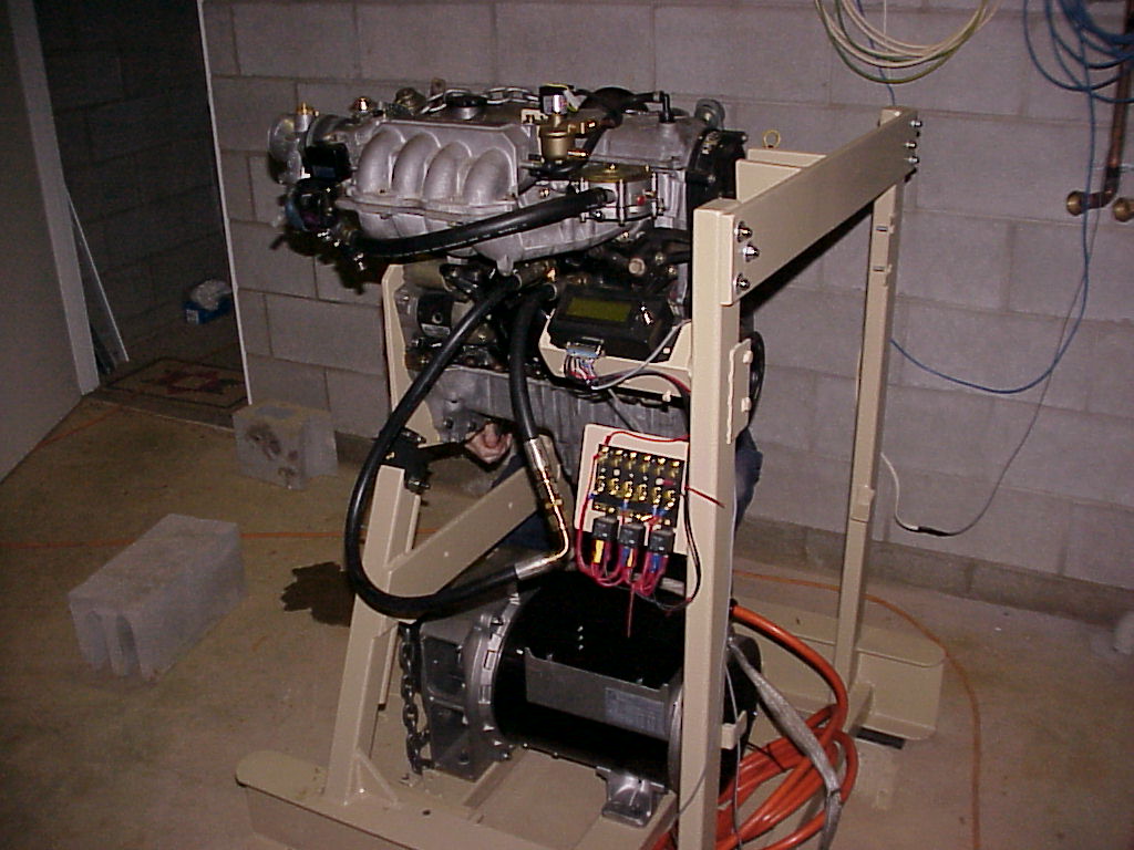
| Oblique view. The extra oil tank and cooler not fitted yet, nor is the computer control system, the exhaust heat exchanger, safety guards, air cleaner etc! |
| Virtually finished, one of the sub-boards. Doors left to go on but otherwise done. |
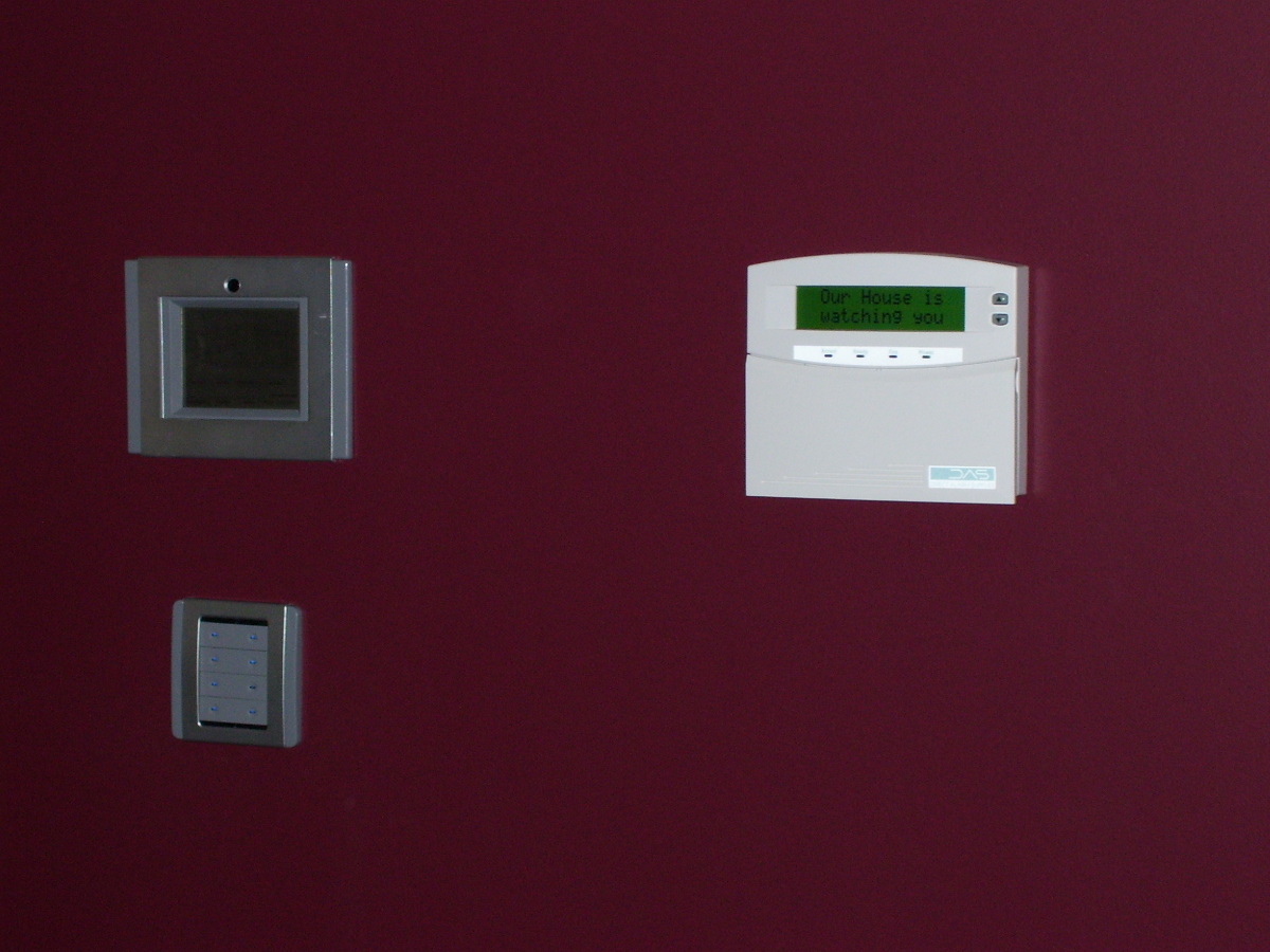
| Lounge room, showing Touch-Screen, 8-gang NEO and one of the alarm control panels |
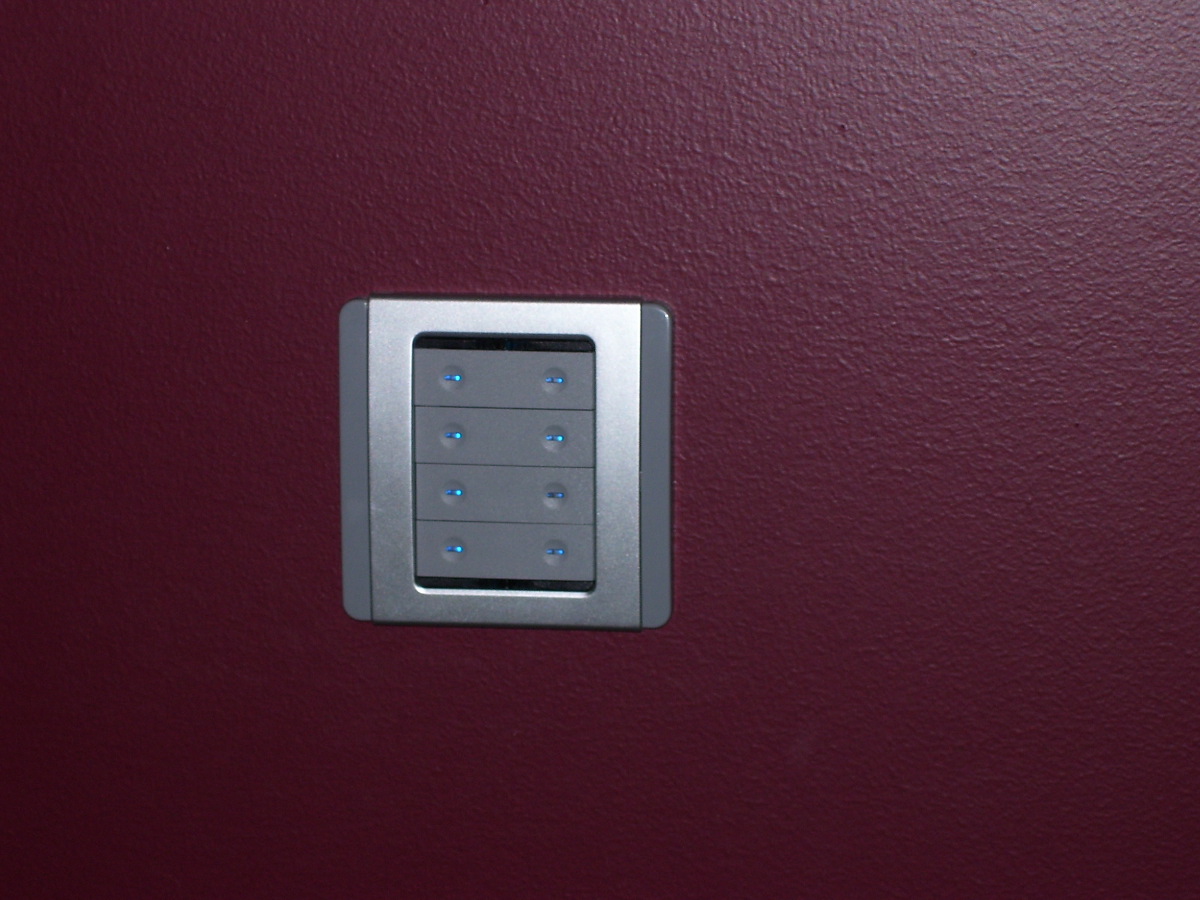
| Closeup of an 8-gang NEO, mounted. |
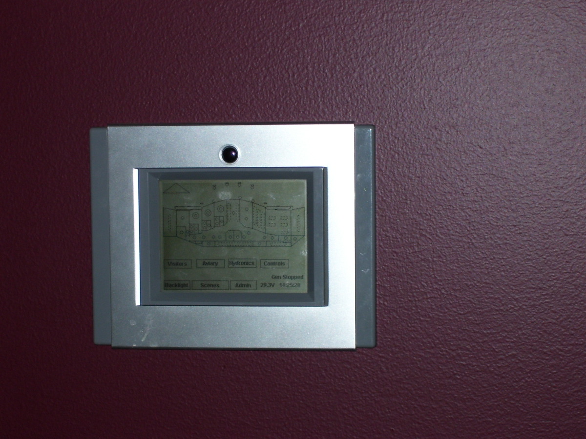
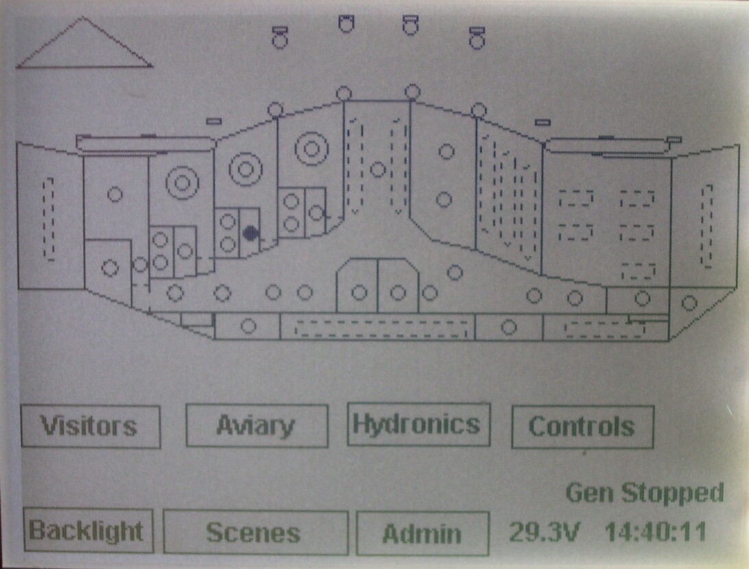
| Didn't notice the grubby marks until I'd taken the photo. Touch-screen in "normal" display mode. |
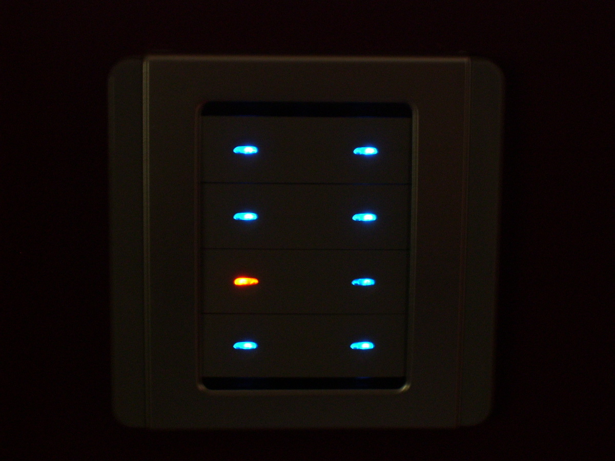
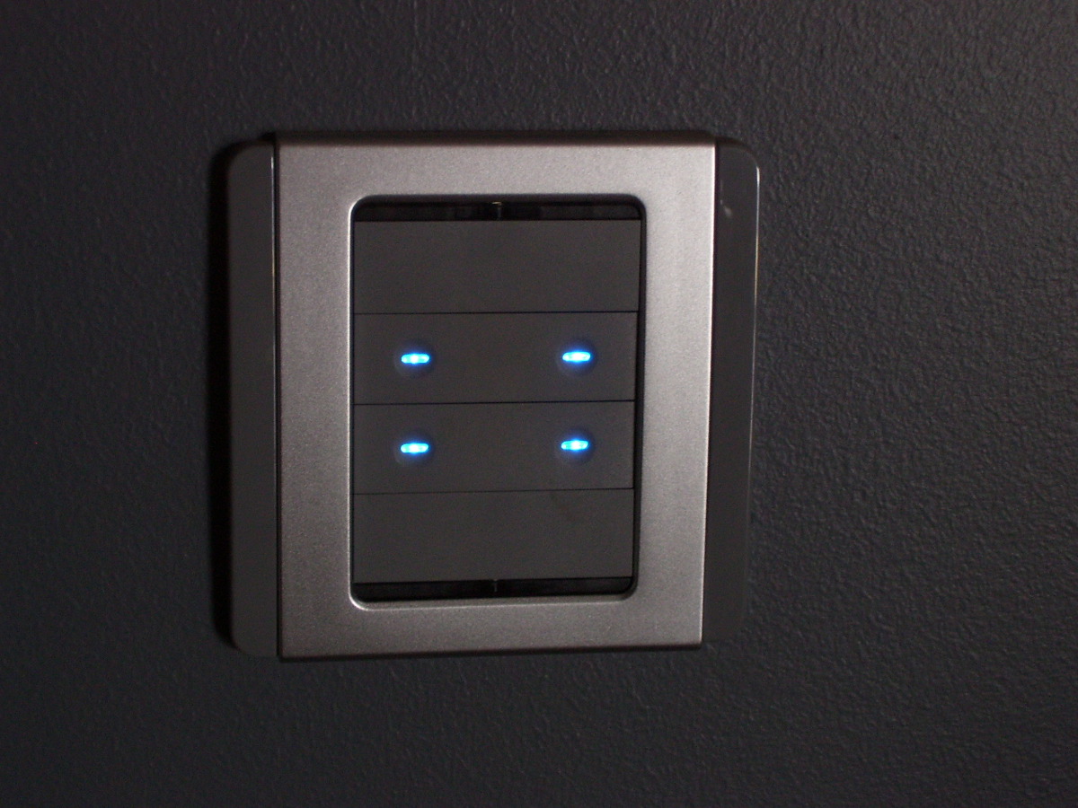
| The NEO switches are quite clear in the dark. Fully programmable, but we've chosen blue for inactive and orange for active. Yes, they dim at night, or on command. |
| All the switches (2, 4 and 8 gang) are the same size and can be interchanged if required. |
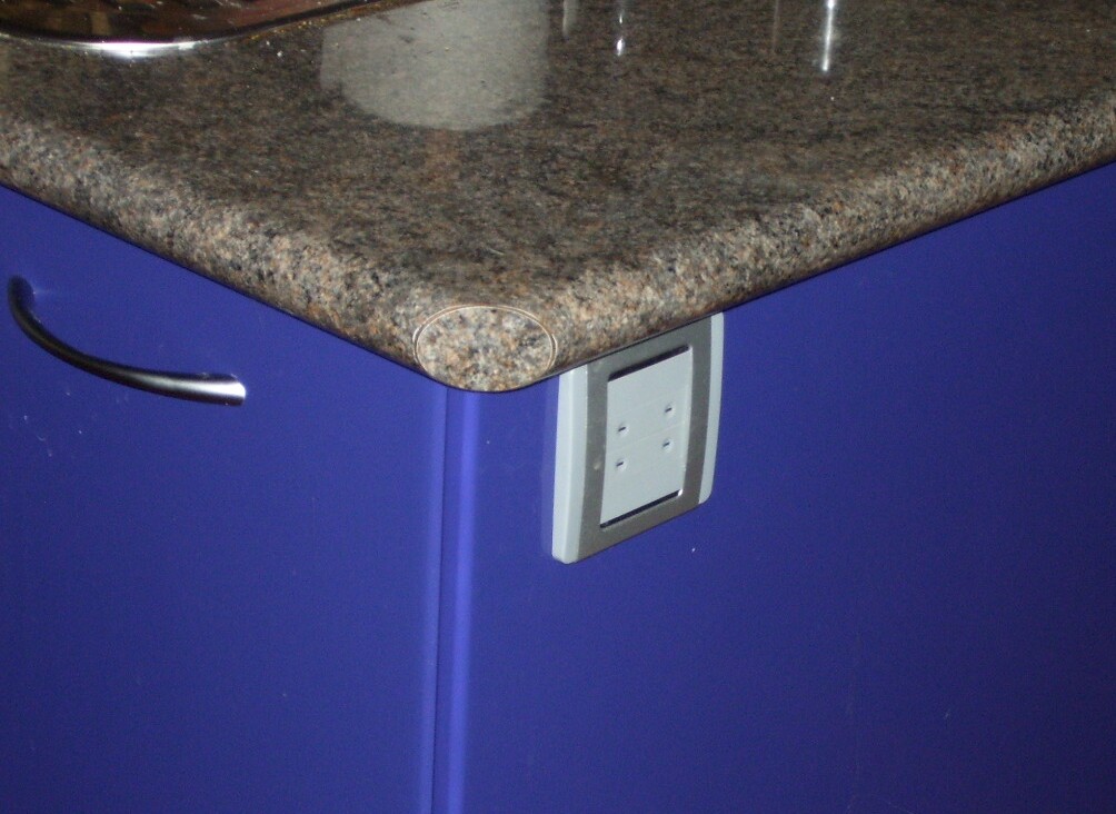
| Even mounted discretely on the side of a kitchen island. |
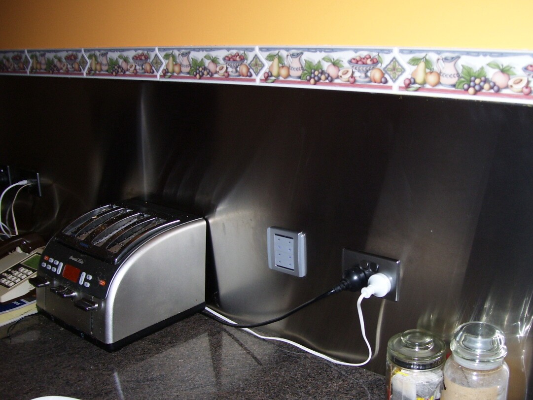
| Or in the stainless-steel kitchen splashbacks. We used "Satin-Chrome" GPOs, network, phone and TV outlet cover plates, which match nicely. |
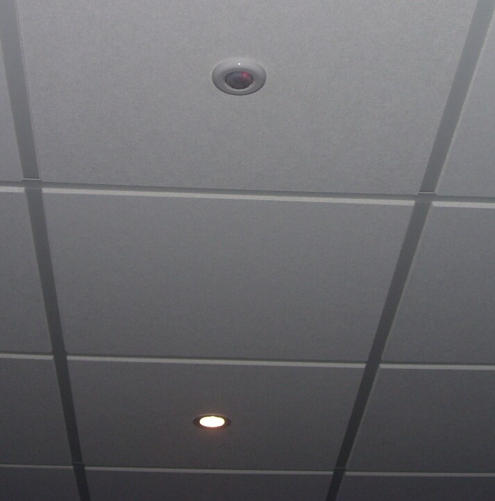
| Many rooms have "occupancy sensors" which turn on and off (or fade up and down) lights automatically. |
| The B&W touchscreen is smaller, cheaper and now obsolete, but was the only one available at the time. Even so, it still makes a useful control and status/display point. Fully customisable of course. These are some of the 30 odd screens we've written. |
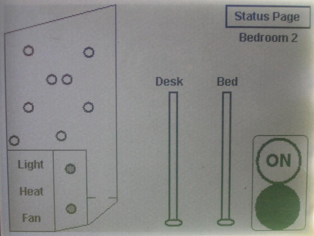
| Most rooms have "closeup" control pages. Each room can have its power turned on and off seperately, bathroom lights, heaters, fans etc seen and controlled, dimmers adjusted etc. |
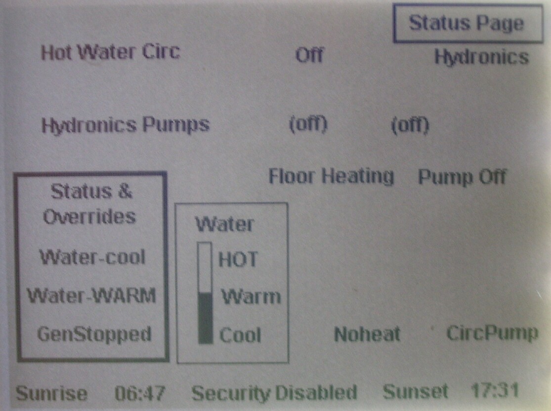
| One of the more technical display pages so I can see where the heating system is up to. |
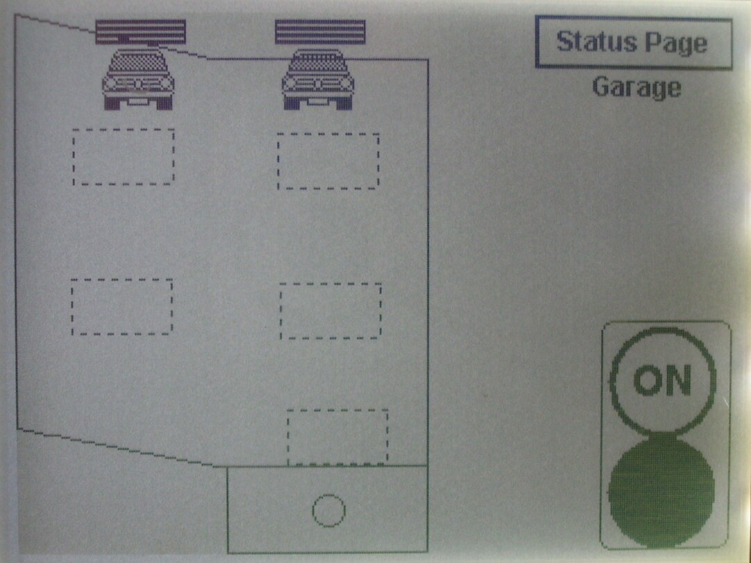
| Garage lights are all individually controllable, opening and closing panel-tilt doors etc remotely via cbus. |